element14 Community
element14 Community
    Register Log In
  • Site
  • Search
  • Log In Register
  • About Us
  • Community Hub
    Community Hub
    • What's New on element14
    • Feedback and Support
    • Benefits of Membership
    • Personal Blogs
    • Members Area
    • Achievement Levels
  • Learn
    Learn
    • Ask an Expert
    • eBooks
    • element14 presents
    • Learning Center
    • Tech Spotlight
    • STEM Academy
    • Webinars, Training and Events
    • Learning Groups
  • Technologies
    Technologies
    • 3D Printing
    • FPGA
    • Industrial Automation
    • Internet of Things
    • Power & Energy
    • Sensors
    • Technology Groups
  • Challenges & Projects
    Challenges & Projects
    • Design Challenges
    • element14 presents Projects
    • Project14
    • Arduino Projects
    • Raspberry Pi Projects
    • Project Groups
  • Products
    Products
    • Arduino
    • Avnet Boards Community
    • Dev Tools
    • Manufacturers
    • Multicomp Pro
    • Product Groups
    • Raspberry Pi
    • RoadTests & Reviews
  • Store
    Store
    • Visit Your Store
    • Choose another store...
      • Europe
      •  Austria (German)
      •  Belgium (Dutch, French)
      •  Bulgaria (Bulgarian)
      •  Czech Republic (Czech)
      •  Denmark (Danish)
      •  Estonia (Estonian)
      •  Finland (Finnish)
      •  France (French)
      •  Germany (German)
      •  Hungary (Hungarian)
      •  Ireland
      •  Israel
      •  Italy (Italian)
      •  Latvia (Latvian)
      •  
      •  Lithuania (Lithuanian)
      •  Netherlands (Dutch)
      •  Norway (Norwegian)
      •  Poland (Polish)
      •  Portugal (Portuguese)
      •  Romania (Romanian)
      •  Russia (Russian)
      •  Slovakia (Slovak)
      •  Slovenia (Slovenian)
      •  Spain (Spanish)
      •  Sweden (Swedish)
      •  Switzerland(German, French)
      •  Turkey (Turkish)
      •  United Kingdom
      • Asia Pacific
      •  Australia
      •  China
      •  Hong Kong
      •  India
      •  Korea (Korean)
      •  Malaysia
      •  New Zealand
      •  Philippines
      •  Singapore
      •  Taiwan
      •  Thailand (Thai)
      • Americas
      •  Brazil (Portuguese)
      •  Canada
      •  Mexico (Spanish)
      •  United States
      Can't find the country/region you're looking for? Visit our export site or find a local distributor.
  • Translate
  • Profile
  • Settings
Avnet Boards Forums
  • Products
  • Dev Tools
  • Avnet Boards Community
  • Avnet Boards Forums
  • More
  • Cancel
Avnet Boards Forums
Software Application Development MiniZed SDK LED Blinking
  • Forum
  • Documents
  • Members
  • Mentions
  • Sub-Groups
  • Tags
  • More
  • Cancel
  • New
Join Avnet Boards Forums to participate - click to join for free!
Actions
  • Share
  • More
  • Cancel
Forum Thread Details
  • Replies 10 replies
  • Subscribers 329 subscribers
  • Views 3006 views
  • Users 0 members are here
  • minized sdk led blinking helloworld xgpio gpio
Related

MiniZed SDK LED Blinking

alphatozeta@yahoo.com
alphatozeta@yahoo.com over 6 years ago

I cloned and went through the example "Prebuilt Platforms Using Hardware Definition Files (HDFs)" https://github.com/Avnet/hdl/tree/mz_petalinux_2018_2 .

I can get the Hello World printf() statements to work and have been trying to blink the Red/Green LED's. I've tried to follow the only examples I can find but none of them are specific for the minized.

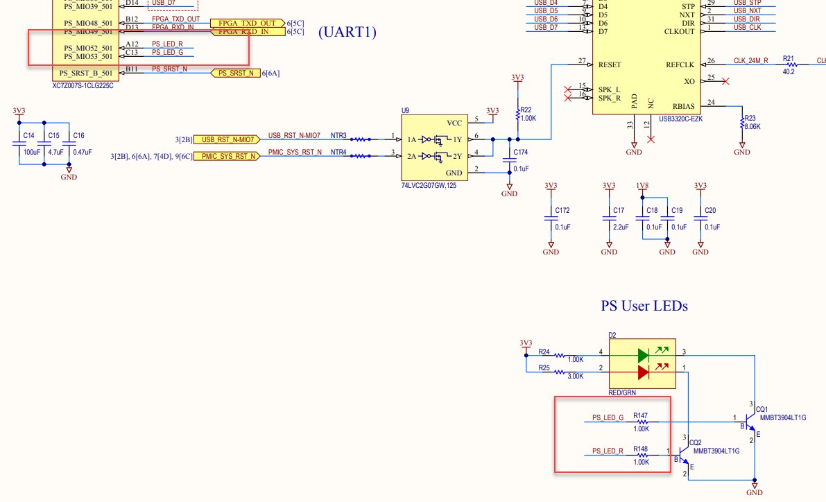
The examples I can find write directly to a pin number and use XGpioPs_LookupConfig(XPAR_PS7_GPIO_0_DEVICE_ID); to setup the I/O. I think I should be using  XPAR_AXI_GPIO_0_DEVICE_ID.

Nothing works and I have no idea what to put for the pin number. My code is below.

Help please!


//------------------------------------------------------------------------------------------------------------------------------

#include <stdio.h>

#include <math.h>

#include "platform.h"

#include "xil_printf.h"

#include "xgpiops.h"

////#include "xparameters_ps.h"

#include "xparameters.h"


int main()

{

    XGpioPs_Config *GPIO_Config;

    XGpioPs my_Gpio;

    int Status;

    int LED_ONOFF = 0;

    int i,j;

    int portpin = 0;

    float raddeg,deg,num;

    init_platform();


    print("\n\rHello World\n\r");


    // Port Setup

     //GPIO_Config = XGpioPs_LookupConfig(XPAR_PS7_GPIO_0_DEVICE_ID);

    GPIO_Config = XGpioPs_LookupConfig(XPAR_AXI_GPIO_0_DEVICE_ID);

    Status = XGpioPs_CfgInitialize(&my_Gpio, GPIO_Config,GPIO_Config->BaseAddr);

    XGpioPs_SetDirection(&my_Gpio,portpin,1);        //Set Pin Direction. (1 == output)

    XGpioPs_SetOutputEnablePin(&my_Gpio,portpin,1);    //Enable output pin


    printf("GPIO Setup Completed\n\r");


   //Blink the LED 5 times and delay blink by printing to screen.

    for(j=0;j<5;j++)

    {

        for (i=0;i<=4000;i++)

        {

           printf("LED=%d\r",LED_ONOFF);

        }

        printf("\nLEDChange\n\r");

        if(LED_ONOFF == 1)

            {

            LED_ONOFF = 0;

            printf("LED is OFF\n\r");

            }

        else

            {

            LED_ONOFF = 1;

            printf("LED is ON\n\r");

            }


        XGpioPs_WritePin(&my_Gpio,portpin,LED_ONOFF);

    }


cleanup_platform();

return 0;

}

  • Sign in to reply
  • Cancel
  • jafoste4
    jafoste4 over 6 years ago

    Hi,


    I would suggest you start by taking a look at the following 2 blogs.


    https://forums.xilinx.com/t5/Xcell-Daily-Blog-Archived/Using-the-MicroZed-Button-for-Input-Adam-Taylor-s-MicroZed/ba-p/3…

    https://forums.xilinx.com/t5/Xcell-Daily-Blog-Archived/Driving-the-Zynq-SoC-s-GPIO-Adam-Taylor-s-MicroZed-Chronicles/ba-…


    -Josh

    • Cancel
    • Vote Up 0 Vote Down
    • Sign in to reply
    • Cancel
  • alphatozeta@yahoo.com
    alphatozeta@yahoo.com over 6 years ago in reply to jafoste4

    I tried the LED example but its for the microzed. It doesn't change the LED. I am not sure how you determine what "pin" to write to. One of the system.mss In the examples showed using  "Type_of_board = XGetPlatform_Info();"  to determine the type of board and set the output pin = 10 for the baord type that function returned.

    I have not idea if this is correct or if the microzed example translates to a minized board.


    My code:


    #include "xgpiops.h"

    #include "xstatus.h"

    #include "xplatform_info.h"

    //#include <xil_printf.h>

    #include <stdio.h>

    #include <math.h>


    #define ledpin 10


    XGpioPs Gpio;


    int main()

    {

        int Status;


        XGpioPs_Config *GPIOConfigPtr;


        GPIOConfigPtr = XGpioPs_LookupConfig(XPAR_PS7_GPIO_0_DEVICE_ID);


        Status = XGpioPs_CfgInitialize(&Gpio, GPIOConfigPtr, GPIOConfigPtr->BaseAddr);


        if (Status != XST_SUCCESS) {


        return XST_FAILURE;


        }


        printf("XGpio Setup Successful.\n\r");


        XGpioPs_SetDirectionPin(&Gpio, ledpin, 1);


        XGpioPs_SetOutputEnablePin(&Gpio, ledpin, 1);


        XGpioPs_WritePin(&Gpio, ledpin, 0x0);


        return 0;

    }

    • Cancel
    • Vote Up 0 Vote Down
    • Sign in to reply
    • Cancel
  • jafoste4
    jafoste4 over 6 years ago in reply to alphatozeta@yahoo.com

    Hi Tom,


    How did you configure your Hardware Platform? How is MIO 52 and MIO 53 connected? Assuming they are connected to PS GPIO, change

    #define ledpin 10


    to

    #define ledpin 52


    or


    #define ledpin 53


    -Josh

    • Cancel
    • Vote Up 0 Vote Down
    • Sign in to reply
    • Cancel
  • alphatozeta@yahoo.com
    alphatozeta@yahoo.com over 6 years ago in reply to jafoste4

    I cloned and went through the example "Prebuilt Platforms Using Hardware Definition Files (HDFs)" https://github.com/Avnet/hdl/tree/mz_petalinux_2018_2

    and went through that example. It runs "HelloWorld" prints.

    How do I find what MIO 52 and MIO 53 are? What are they?

    • Cancel
    • Vote Up 0 Vote Down
    • Sign in to reply
    • Cancel
  • jafoste4
    jafoste4 over 6 years ago in reply to alphatozeta@yahoo.com

    Hi Tom,


    MIO are Multiplected I/O. Basically processor specific pins. Take a look at this https://www.realdigital.org/doc/4b3000d07f821a225e90486b4ea33815


    You seem fairly new to ZYNQ. If I make may a suggestion, please complete the Developing Zynq Hardware Speedway located here | Zedboard This will help you through the basics of FPGA development.


    -Josh

    • Cancel
    • Vote Up 0 Vote Down
    • Sign in to reply
    • Cancel
  • alphatozeta@yahoo.com
    alphatozeta@yahoo.com over 6 years ago in reply to jafoste4

    That's a good reference...Thanks.

    I got the LED to blink using 52 & 53. The realdigital article says the LED is on 16,17&18 for that board. How do I find that for the MiniZed board? I looked at everything I could find in Vivado connected to those signals but didn't see "MIOxx" anywhere.

    Thanks!

    • Cancel
    • Vote Up 0 Vote Down
    • Sign in to reply
    • Cancel
  • jafoste4
    jafoste4 over 6 years ago in reply to alphatozeta@yahoo.com

    Hi,


    I referenced the schematic for this information.

    image

    -Josh

    • Cancel
    • Vote Up 0 Vote Down
    • Sign in to reply
    • Cancel
  • alphatozeta@yahoo.com
    alphatozeta@yahoo.com over 6 years ago in reply to jafoste4

    Any hints about how to write to the other "PL" Red/Green LED on axi_gpio_0 ? I assume these go through another path from the processor through the fabric to LED?

    Thanks...Tom


    imageimage

    • Cancel
    • Vote Up 0 Vote Down
    • Sign in to reply
    • Cancel
  • jafoste4
    jafoste4 over 6 years ago in reply to alphatozeta@yahoo.com

    Hi Tom,


    If you go through the Developing Zynq Hardware Speedway, it shows how we connected that inteface up through the PL.


    Then if you go through the Developing Zynq Software Speedway it takes you through an exercise of turning that LED off and on.

    Training and Videos | Zedboard

    Please start there


    -Josh

    • Cancel
    • Vote Up 0 Vote Down
    • Sign in to reply
    • Cancel
  • javagoza
    javagoza over 2 years ago in reply to alphatozeta@yahoo.com

    In case anyone is still wondering how to do this I have made a couple of examples to turn on those LEDs from Programmable Logic. See:  P2P3 Getting Started. Clockless Hardware Blinky on the Avnet Minized 

    • Cancel
    • Vote Up 0 Vote Down
    • Sign in to reply
    • Cancel
element14 Community

element14 is the first online community specifically for engineers. Connect with your peers and get expert answers to your questions.

  • Members
  • Learn
  • Technologies
  • Challenges & Projects
  • Products
  • Store
  • About Us
  • Feedback & Support
  • FAQs
  • Terms of Use
  • Privacy Policy
  • Legal and Copyright Notices
  • Sitemap
  • Cookies

An Avnet Company © 2025 Premier Farnell Limited. All Rights Reserved.

Premier Farnell Ltd, registered in England and Wales (no 00876412), registered office: Farnell House, Forge Lane, Leeds LS12 2NE.

ICP 备案号 10220084.

Follow element14

  • X
  • Facebook
  • linkedin
  • YouTube