element14 Community
element14 Community
    Register Log In
  • Site
  • Search
  • Log In Register
  • Community Hub
    Community Hub
    • What's New on element14
    • Feedback and Support
    • Benefits of Membership
    • Personal Blogs
    • Members Area
    • Achievement Levels
  • Learn
    Learn
    • Ask an Expert
    • eBooks
    • element14 presents
    • Learning Center
    • Tech Spotlight
    • STEM Academy
    • Webinars, Training and Events
    • Learning Groups
  • Technologies
    Technologies
    • 3D Printing
    • FPGA
    • Industrial Automation
    • Internet of Things
    • Power & Energy
    • Sensors
    • Technology Groups
  • Challenges & Projects
    Challenges & Projects
    • Design Challenges
    • element14 presents Projects
    • Project14
    • Arduino Projects
    • Raspberry Pi Projects
    • Project Groups
  • Products
    Products
    • Arduino
    • Avnet & Tria Boards Community
    • Dev Tools
    • Manufacturers
    • Multicomp Pro
    • Product Groups
    • Raspberry Pi
    • RoadTests & Reviews
  • About Us
  • Store
    Store
    • Visit Your Store
    • Choose another store...
      • Europe
      •  Austria (German)
      •  Belgium (Dutch, French)
      •  Bulgaria (Bulgarian)
      •  Czech Republic (Czech)
      •  Denmark (Danish)
      •  Estonia (Estonian)
      •  Finland (Finnish)
      •  France (French)
      •  Germany (German)
      •  Hungary (Hungarian)
      •  Ireland
      •  Israel
      •  Italy (Italian)
      •  Latvia (Latvian)
      •  
      •  Lithuania (Lithuanian)
      •  Netherlands (Dutch)
      •  Norway (Norwegian)
      •  Poland (Polish)
      •  Portugal (Portuguese)
      •  Romania (Romanian)
      •  Russia (Russian)
      •  Slovakia (Slovak)
      •  Slovenia (Slovenian)
      •  Spain (Spanish)
      •  Sweden (Swedish)
      •  Switzerland(German, French)
      •  Turkey (Turkish)
      •  United Kingdom
      • Asia Pacific
      •  Australia
      •  China
      •  Hong Kong
      •  India
      •  Korea (Korean)
      •  Malaysia
      •  New Zealand
      •  Philippines
      •  Singapore
      •  Taiwan
      •  Thailand (Thai)
      • Americas
      •  Brazil (Portuguese)
      •  Canada
      •  Mexico (Spanish)
      •  United States
      Can't find the country/region you're looking for? Visit our export site or find a local distributor.
  • Translate
  • Profile
  • Settings
Avnet Boards Forums
  • Products
  • Dev Tools
  • Avnet & Tria Boards Community
  • Avnet Boards Forums
  • More
  • Cancel
Avnet Boards Forums
Ultra96 Hardware Design Ultra96's UART0 as serial terminal
  • Forum
  • Documents
  • Members
  • Mentions
  • Sub-Groups
  • Tags
  • More
  • Cancel
  • New
Join Avnet Boards Forums to participate - click to join for free!
Actions
  • Share
  • More
  • Cancel
Forum Thread Details
  • State Verified Answer
  • Replies 16 replies
  • Answers 1 answer
  • Subscribers 349 subscribers
  • Views 3539 views
  • Users 0 members are here
Related

Ultra96's UART0 as serial terminal

reis220
reis220 over 6 years ago

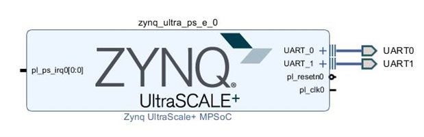
Hello! Is it possible to use UART0 of Ultra96 as serial console? Using Ultra96's BSP the UART0 is connected to bluetooth and i can't use it as serial terminal. Can you tell me how do i use both UARTs as serial terminals?

  • Sign in to reply
  • Cancel
Parents
  • jafoste4
    0 jafoste4 over 6 years ago

    Hi,


    That would require you going in and modifying the Hardware Platform in Vivado to connect UART0 to one of the various UART outputs on the board. You would lose all functionality of Bluetooth doing so.


    -Josh

    • Cancel
    • Vote Up 0 Vote Down
    • Sign in to reply
    • Reject Answer
    • Cancel
  • reis220
    0 reis220 over 6 years ago in reply to jafoste4

    Like this? Both UARTs are routed to EMIO.


    image

    • Cancel
    • Vote Up 0 Vote Down
    • Sign in to reply
    • Verify Answer
    • Cancel
  • jafoste4
    0 jafoste4 over 6 years ago in reply to reis220

    Hi Joao,


    If you route both to EMIO, you will need to write constraints to send them to the UART pins on the 40 pin low speed connector. You be able to use the 3 pin uart output that is easily accessible by the jtag pod. Instead you will have to route fly wires to these pins.


    -Josh

    • Cancel
    • Vote Up 0 Vote Down
    • Sign in to reply
    • Verify Answer
    • Cancel
  • reis220
    0 reis220 over 6 years ago in reply to jafoste4

    Yes, i've written constraints to both UARTs.

    image

    • Cancel
    • Vote Up 0 Vote Down
    • Sign in to reply
    • Verify Answer
    • Cancel
Reply
  • reis220
    0 reis220 over 6 years ago in reply to jafoste4

    Yes, i've written constraints to both UARTs.

    image

    • Cancel
    • Vote Up 0 Vote Down
    • Sign in to reply
    • Verify Answer
    • Cancel
Children
  • jafoste4
    0 jafoste4 over 6 years ago in reply to reis220

    Assuming your constraints are correct, dependent on how you setup your bsp in SDK and dependent on which UART your connected to via flywires, you should be able to use both UARTs.


    -Josh

    • Cancel
    • Vote Up 0 Vote Down
    • Sign in to reply
    • Verify Answer
    • Cancel
  • 100sbeaudoin
    0 100sbeaudoin over 6 years ago in reply to jafoste4

    In my personnal opinion, you should leave the UART1 connected to the 3pin connector and leave it as the linux console; it is a vital debugging tool because you have all the traces since the press of the power button. Secondly, in my personnal opinion, I hate all the bluetooth retry/error messages popping in the console when the UART0 is not connected to bluetooth, even if I don't use it. If you need extra UARTs, like for debugging the RPUs, consider instantiating two AXI UART 16650 in the FPGA and routing the pins to the low speed 40 pin header. They will be automatically recognised in the subsequent steps in petalinux/XSDK as uarts, just like the genuine ones. If you don't have anything to connect to the header, and assuming you want the uarts for the RPUs, and for example you use FreeRTOS, you can change the std in/out in the freertos bsp settings to 'coresight' instead of ps_uart1 or ps_uart0 (or any AXI UART16650 or AXI Uartlite). Coresight is a jtag virtual uart. So if you bought the jtag pod (which you should definitely), you end up with ~3~ uarts. In SDK, you can open a window and connect to the jtag uarts

    • Cancel
    • Vote Up 0 Vote Down
    • Sign in to reply
    • Verify Answer
    • Cancel
  • reis220
    0 reis220 over 6 years ago in reply to 100sbeaudoin

    100sbeaudoin  wrote:

    If you need extra UARTs, like for debugging the RPUs, consider instantiating two AXI UART 16650 in the FPGA and routing the pins to the low speed 40 pin header. They will be automatically recognised in the subsequent steps in petalinux/XSDK as uarts, just like the genuine ones.

    Do you mean one UART 16550 for UART0 and another UART 16550 for UART1?

    What is the difference between having an UART 16550 connected out of PS or having just ps_uart? The Ultra96's BSP original block design has one ps_uart0 connected to a UART 16550 IP and another ps_uart1 connected just to external headers, but i don't know the difference it makes having one or the other.


    100sbeaudoin  wrote:

    If you don't have anything to connect to the header, and assuming you want the uarts for the RPUs, and for example you use FreeRTOS, you can change the std in/out in the freertos bsp settings to 'coresight' instead of ps_uart1 or ps_uart0 (or any AXI UART16650 or AXI Uartlite). Coresight is a jtag virtual uart. So if you bought the jtag pod (which you should definitely), you end up with ~3~ uarts. In SDK, you can open a window and connect to the jtag uarts

    I am using one core from APU running Linux and another core running Erika RTOS, so my purpose is to have both UARTs to serve as serial consoles from APU. I intend to have both UARTs accessible by the low speed headers.


    When i see the bootload of Linux, it only says that (even though both ttyPS* are recognized) only ttyPS0 (aka UART1) is enabled. I've changed the design to the one i've shown above, and used the provided Ultra96 BSP to create a petalinux project. But then, i configured the project based on the customized hdf (the one based from the design above), but still ttyPS1 doesn't enable.

    • Cancel
    • Vote Up 0 Vote Down
    • Sign in to reply
    • Verify Answer
    • Cancel
  • 100sbeaudoin
    0 100sbeaudoin over 6 years ago in reply to reis220

    Do you mean one UART 16550 for UART0 and another UART 16550 for UART1?

    When I talk about uart0 and uart1, I'm referring to the two phycical uarts that exists in the PS.

    What is the difference between having an UART 16550 connected out of PS or having just ps_uart?

    An uart 16500 is a IP block that you instantiate in the FPGA that is connected to the axi port of the zynq. To the eye of a processor in the PS (being the APU running linux of any of the RPUs running an instance of the RTOS of you choice) there is virtually no difference between using the UART0, the UART1 or any other instance of a uart in the FPGA.

    I am using one core from APU running Linux and another core running Erika RTOS, so my purpose is to have both UARTs to serve as serial consoles from APU. I intend to have both UARTs accessible by the low speed headers.

    Let's say you prefer not using any uart from the FPGA, you can effectively route the RX and TX pins of UART0 and UART1 as emio to the low speed header. If I'm not mistaken it's what they do in the vivado project included in the Ultra96's BSP. Then, your APU core running linux can use one and your other core running your RTOS can use the other, no worries with that.


    But then, I'm asking myself why you would use 'one' core of the APU to run linux, and another one to run your RTOS in the first place. If you are not super experienced, from my experience it's easier to simply use the default configuration of petalinux and let linux take control of the four APU cores in an SMP configuration. If you want to run and RTOS flavor of your choice, the two RPU cores have been designed especially for that purpose. Again, if not too much experienced, try out FreeRTOS which is directly supported in the Xilinx ecosystem.


    What I meant in my previous message is that, if you have the JTAG pod, then you should really let the UART1 routed to the 3 pin connector (that connects to the pod) because this is what that connector was intended for. (((back when they launched the ultra96, the jtag pod was not yet available for purchase, so in the bsp whey routed the uarts to the low speed header, because 96board uart adapters where available))).

    When i see the bootload of Linux, it only says that (even though both ttyPS* are recognized) only ttyPS0 (aka UART1) is enabled. I've changed the design to the one i've shown above, and used the provided Ultra96 BSP to create a petalinux project. But then, i configured the project based on the customized hdf (the one based from the design above), but still ttyPS1 doesn't enable.

    I'm not exactly sure to follow you here. When you create a petalinux project from the HDF, the HDF file contains the information about every peripheral on the board (including the ones you instantiate in the FPGA). That way, you project is aware there are two UARTS (possibly more if you instantiate uart 16550). In the 'petalinux-config' menu, you can see all the UARTs available in the <Subsystem AUTO Hardware Settings ---> Serial Settings > section. There, you select which uart you want to use for the terminal. The uart selected as terminal will be, well, a terminal! You won't be able to open(), write(), read(), close() in a linux application because the OS will ave control of it.


    Don't forget that in the zcu100-revc.dtsi overlay included when you take the petalinux project provided in the bsp, the uart0 node is appended with this information :

    &uart0 {

         bluetooth {

         compatible = "ti,wl1831-st";

         enable-gpios = <&gpio 8 0>;

         };

    };


    What this will do is at boot time the uart0 will be controlled by the "ti,wl1831-st" driver for bluetooth. Thats why you can't use it freely after that.


    Personnal opinion :

    I use UART1 as the linux terminal because its the one routed to the jtag pod. I let the UART0 connected to the bluetooth chip like in the BSP, because the error messages about bluetooth anoys me, and because I don't want to alter it's default attribution in the dtsi. When I need extra UART output for RPU0 and RPU1, I instantiate one or two  AXI UART 16550, and select them as the 'stdin and stdout' in the FreeRTOS configuration in XSDK and route their signals to the low speed header.


    Ho, and before I forget! For example, when you create a FreeRTOS project targeting an RPU in XSDK, you can select the stdin and stdout to be using the 'coresight' driver instead of UART0, UART1 or any uart in the FPGA. This is something called uart over jtag, and it's a great feature. The 'coresight' driver is the one that takes care of that. So, with just the JTAG pod, you can have your linux terminal on UART1, and two virtual UARTs trough the jtag interface for each RPU. That way, you don't even need an extra dongle to plug to the low speed header.


    To know more about it, take a look at : https://www.xilinx.com/html_docs/xilinx2018_1/SDK_Doc/xsct/use_cases/xsdb_using_jtag_uart.html


    I hope all this makes more sense to you now.


    -Simon

    • Cancel
    • Vote Up 0 Vote Down
    • Sign in to reply
    • Verify Answer
    • Cancel
  • reis220
    0 reis220 over 6 years ago in reply to 100sbeaudoin

    100sbeaudoin  wrote:

    An uart 16500 is a IP block that you instantiate in the FPGA that is connected to the axi port of the zynq. To the eye of a processor in the PS (being the APU running linux of any of the RPUs running an instance of the RTOS of you choice) there is virtually no difference between using the UART0, the UART1 or any other instance of a uart in the FPGA.

    What i intended to question was: functionally, what is the difference between an UART in FPGA or an UART in PS? Other questions is: with FPGA UARTs, i can extend the number of UARTs of my board besides the PS UARTs?


    100sbeaudoin  wrote:

    But then, I'm asking myself why you would use 'one' core of the APU to run linux, and another one to run your RTOS in the first place. If you are not super experienced, from my experience it's easier to simply use the default configuration of petalinux and let linux take control of the four APU cores in an SMP configuration. If you want to run and RTOS flavor of your choice, the two RPU cores have been designed especially for that purpose. Again, if not too much experienced, try out FreeRTOS which is directly supported in the Xilinx ecosystem.

    I pretend to run an AMP configuration where each core from APU has its own OS (or VM). More specifically, run Jailhouse hypervisor beneath Linux and ErikaRTOS to test some side-channels intra-core, so i don't intend to use RPU.


    100sbeaudoin  wrote:

    Don't forget that in the zcu100-revc.dtsi overlay included when you take the petalinux project provided in the bsp, the uart0 node is appended with this information :

    &uart0 {

         bluetooth {

         compatible = "ti,wl1831-st";

         enable-gpios = <&gpio 8 0>;

         };

    };


    What this will do is at boot time the uart0 will be controlled by the "ti,wl1831-st" driver for bluetooth. Thats why you can't use it freely after that.

    Ok, that is something i didn't notice! So, if i want to change the uart0 to a serial terminal (just like uart1) what changes must i make to the device tree? I suppose that the device tree i must change is system-user.dtsi, isn't it?


    • Cancel
    • Vote Up 0 Vote Down
    • Sign in to reply
    • Verify Answer
    • Cancel
  • reis220
    0 reis220 over 6 years ago in reply to reis220

    And i don't have with me a JTAG pod. So, i am using 2 FT232RL modules connected to the low speed headers.

    • Cancel
    • Vote Up 0 Vote Down
    • Sign in to reply
    • Verify Answer
    • Cancel
  • 100sbeaudoin
    0 100sbeaudoin over 6 years ago in reply to reis220

    reis220  wrote:


    100sbeaudoin   wrote:

    An uart 16500 is a IP block that you instantiate in the FPGA that is connected to the axi port of the zynq. To the eye of a processor in the PS (being the APU running linux of any of the RPUs running an instance of the RTOS of you choice) there is virtually no difference between using the UART0, the UART1 or any other instance of a uart in the FPGA.

    What i intended to question was: functionally, what is the difference between an UART in FPGA or an UART in PS? Other questions is: with FPGA UARTs, i can extend the number of UARTs of my board besides the PS UARTs?


    In terms of functionnality, there will be no difference. The difference is that the PS UART is a peripheral that exists in the silicon of the chip where as the ones in the FPGA will exist as long as the FPGAs bitstream is written. With the fpga, you can in fact extend the number of UARTs, beside the two PS UARTS. The only limit to the number of uarts will be the number of fpga pins on the low speed header!!


    I pretend to run an AMP configuration where each core from APU has its own OS (or VM). More specifically, run Jailhouse hypervisor beneath Linux and ErikaRTOS to test some side-channels intra-core, so i don't intend to use RPU.

    Ok now I get it.


    Ok, that is something i didn't notice! So, if i want to change the uart0 to a serial terminal (just like uart1) what changes must i make to the device tree? I suppose that the device tree i must change is system-user.dtsi, isn't it?

    Yea, system-user.dtsi is the one you want to make modifications into since it is not overwritten by the DTG (datatree generator) each time you issue a "petalinux-config --get-hw-description" command. I am familiar to modify data tree nodes in the system-user.dtsi file to add/overwrite information. But erasing a field is something you should investigate for indeed, because I can't tell you how since I never dit it ;-) . That way you will impeed linux to fuss with ps_uart0 from the beginning.


    "And i don't have with me a JTAG pod. So, i am using 2 FT232RL modules connected to the low speed headers."

    well, in that situation, you indeed have to route the signals through emios to the low speed header!

    • Cancel
    • Vote Up 0 Vote Down
    • Sign in to reply
    • Verify Answer
    • Reject Answer
    • Cancel
  • reis220
    0 reis220 over 6 years ago in reply to 100sbeaudoin

    I've already changed system-user.dtsi and it really deattached the uart from bluetooth driver.


    system-user.dtsi:


    /include/ "system-conf.dtsi"

    /include/ "openamp-overlay.dtsi"

    /{

    };


    &uart0 {

            /delete-node/bluetooth;

        };

    • Cancel
    • Vote Up 0 Vote Down
    • Sign in to reply
    • Verify Answer
    • Cancel
  • reis220
    0 reis220 over 6 years ago in reply to 100sbeaudoin

    I still can't see any characters on the serial terminal connected to UART0.


    When doing "echo test > /dev/ttyPS1", i can see with "cat /proc/tty/driver/xuartps" that the interrupts of UART0 are being triggered and everything supposedly is working fine, but can't see any cahracter on serial terminal. Then, i issued "devmem (uart0_address)", that outputs the control registers, and it tells that both TX and RX are disabled.

    My question is: How do i enable UART0's TX and RX, or, how do i set these bits?


    Ultra96's UART0 as serial terminal


    • Cancel
    • Vote Up 0 Vote Down
    • Sign in to reply
    • Verify Answer
    • Cancel
element14 Community

element14 is the first online community specifically for engineers. Connect with your peers and get expert answers to your questions.

  • Members
  • Learn
  • Technologies
  • Challenges & Projects
  • Products
  • Store
  • About Us
  • Feedback & Support
  • FAQs
  • Terms of Use
  • Privacy Policy
  • Legal and Copyright Notices
  • Sitemap
  • Cookies

An Avnet Company © 2025 Premier Farnell Limited. All Rights Reserved.

Premier Farnell Ltd, registered in England and Wales (no 00876412), registered office: Farnell House, Forge Lane, Leeds LS12 2NE.

ICP 备案号 10220084.

Follow element14

  • X
  • Facebook
  • linkedin
  • YouTube