


Project's repository: https://github.com/Tai-Min/Azure-Sphere-Home-Process-Controller
Preface
Before I start with the project, I decided to conduct a brief introduction describing what process control is. In industrial process control this means bringing the dynamic object to a certain state and maintain this state as accurately as possible. It is know that actuators are not perfect and e.g the motor on which we give 12 volts will spin differently depending on the load connected to the shaft. This is where process controllers come into action. The task of the controller is to give some output value that will minimize the difference (the error) between out setpoint value and real value (process value). Going back to the example of an motor, let’s assume that we would want to control the angular velocity of the shaft. In this case our setpoint is the angular velocity that we want to keep on the shaft no matter the load, the process value it real angular velocity received from some sensor, e.g rotary encoder and our control value is the voltage that is being feed to the motor e.g 0-12V and our error is the difference that we want to minimize and keep at 0 if possible. The most popular control loop is shown below.
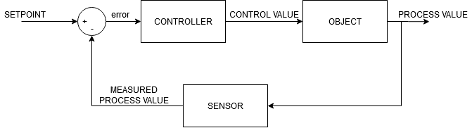
There is a lot of different controllers available in the industry, varying in size, computing power, accuracy and control possibilities but the most popular regulators can be divided into two categories: Continuous and discrete. Continuous regulators are always active and constantly process the error value and are trying to minimize it by increasing or decreasing control output. Their output can take all the values between minimal and maximal control value. The discrete controllers can output only limited number of control values. The most standard example of discrete control is the self-describing two state controller. When error value is below some point, the two state controller turns on actuator and keeps it on until error exceeds some other point and then actuator is turned off. As you have guessed, this type of controller doesn’t really minimize the error but keeps it oscillating between some two values. Its easy tune and for some slow processes good enough. Also, if the actuator has only two available states (e.g home boiler has on/off states) it is necessary to have only two state control as it is not possible to keep continuous control on it.
This project is an implementation of multipurpose industrial controller adapted for home IoT systems, smart home services and assistants andalso can be easily tuned and expanded if necessary.
In home there is a lot of potential for closed loop control systems e.g:
- Gardening:
- Collect rain water to water container and use it to water the plants, create control system which uses predefinied amount of water to water the plants
- Use another control system to flush rain water if there is excees of it and there is possibility of flood around the water container
- Brewing:
- Use PID controller to control the temperature of brewing process
- Wildlife preserving
- Use the controller refill a container with water for wildlife without human interference
- Convenience
- Use the controller to keep the right amount of chlorine in the pool
- Use iot connected two state control system to replace your old thermostate with a smarter one
- Use closed loop control system to keep the right amount of humidity in the room
General assumptions and concepts
The controller
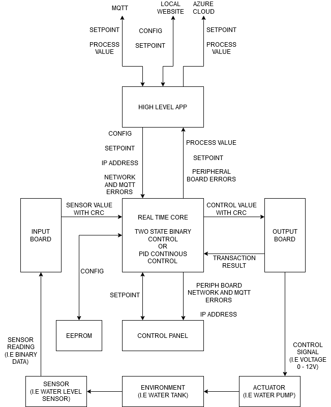
The basis of the project is as the name implies – is the regulator itself. In order to not limit the usage of the project I’ve decided to implemented both continuous and discrete controllers. As the continuous controller I’ve chosen PID controller and as discrete – two state controller. The controller shall be selected from configuration website hosted on the device itself. As the control algorithm is a critical task that requires precision timing and time determinism It was decided to implement it within real time capable core of the Azure Sphere along with all GPIO communication such as communication with sensors and actuators, additional EEPROM memory, 7 segment display, buttons and diodes. The high level core will be responsible for communication with virtual world such as Azure Cloud, IoT devices via MQTT broker and through HTTP server that serves easy access to all of the configuration parameters of the device.
Expansion cards
In order to ensure the largest possible number of supported objects, measurements and actuation were decided to be read from/written to specially designed expansion cards. Thanks to these cards it is possible to control virtually any linear object as long as there is right expansion card for it. To ensure safety of the control process, it was decided to design these cards as separate devices with separate microcontrollers. Thanks to this, communication between the controller and cards could be secured from potential errors and noise with checksum and additional confirmation bits. This method can also be used to check whether cards are connected and are working properly. In case of the card’s fault, the controller goes into failure state and tries to write lowest possible control value into output card. This state can be cleared only by performing hard reset.
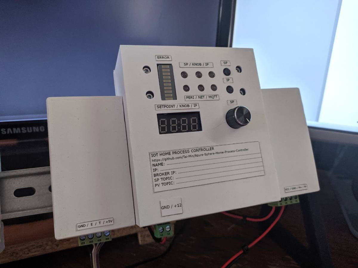
The operator’s panel
The panel (in front of a device) will enable user to check device's IP address and current setpoint via 7 segment display, check control’s error via led bar and check whether there any errors through three error diodes: expansion card’s failure, MQTT not connected and network’s error.
Setpoint setting
To maximize the usability of the project it was decided to let user change the setpoint from three places: MQTT, configuration website and by using the potentiometer located on the housing.
General concept of the device is visible on the diagram below.
MQTT
Nowdays, MQTT can be considered as one of the most popular protocols for communication in home IoT networks. The protocol is used by most popular DIY devices on the market such as those based on ESP8266 and is used to integrate devices with popular home automation services such as Home Assistant and Domoticz. In the project, the controller publishes every 10 seconds the setpoint and proces values to MQTT broker user defined topics and also subscribes setpoint topic for incoming setpoint changes. Use of MQTT lets users who are more experienced with proces control to use these values for coordination with other devices or for supervisory control (e.g optimization algorithms). The controller uses QoS 1 standard of MQTT messaging protocol.
Connectivity
Due to the fact that Azure Sphere does not have a hotspot functionality yet, the connection to the device was decided to be initiated through a hotspot shared from smartphone. By default, the controller tries to connect AzCon network with a password: 12345678. After sharing a hotspot from a smartphone with such parameters the controller will connect to it and it will be possible to obtain it’s local ip address through operator’s panel. Thanks to this it will be possible to access device’s configuration website (local_ip:8181/config) and from it it will be possible to enter our WiFi credentials. After this procedurę, to protect the controller against tampering and increase it’s security (after disconnecting from the main network it will try to connect to AzCon again) the AzCon’s password is changed to the same one that was used when connecting to user’s network. Thanks to this operation, no unauthorized person will be able to take over the controller during the absence of the main network.
Fail safe behavior
To avoid problems that may occur in the event of a power outage, it was decided to add to the project a non-volatile memory that will be used to store the most important controller data such as controller’s configuration, MQTT configuration and informations about expansion cards.
Azure Cloud
Due to the „down to earth” character of the project, it was decided to send to the cloud only informations about the setpoint and proces value.
Electronic designs
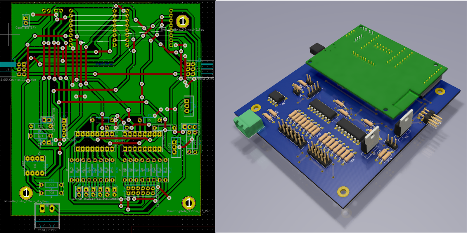
In order to not play with breadboards, it was decided to make a durable, solid project using toner transfer method. All of the boards were designed in KiCad program.
Main board
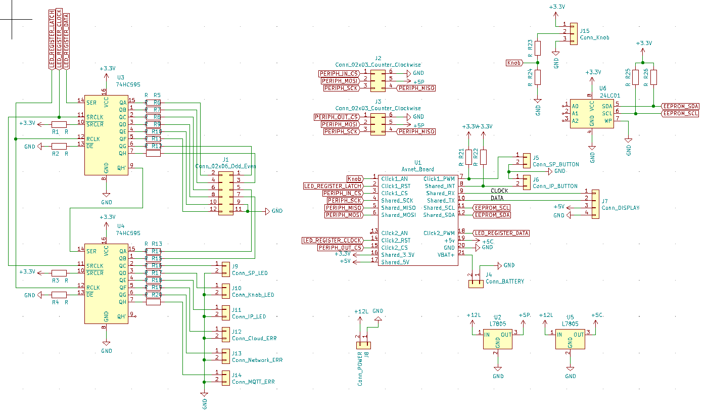
The schematic above shows the controller’s main board. There are two 5V voltage regulators, one for Azure Sphere itself and one for expansion cards. The board also contains 1kb EEPROM memory for configuration, two SIPO registers to control led bar and status diodes, and connectors for buttons, diodes, 7 segment display and potentiometer.
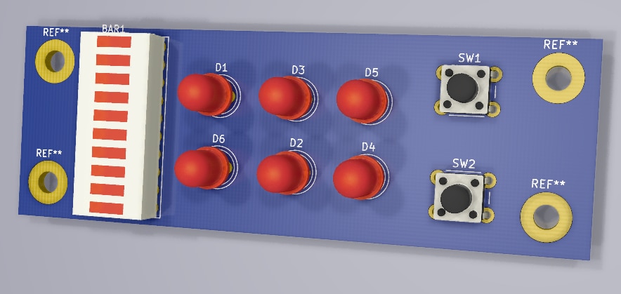
Control panel
The panel has an led bar showing current control error, leds signaling status of the device and buttons responsible for setpoint setting and displaying device’s ip addres to user so configuration website can be accessed.
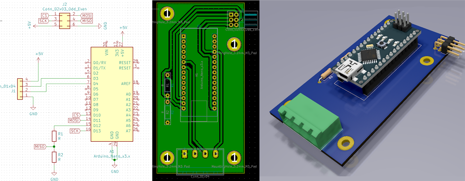
Input peripheral board
As an input, It was decided to use distance measurement from HC-SR04 ultrasonic sensor. In order to measure and secure data Arduino Nano was used. The SPI MISO goes to the motherboard via a voltage divider due to differences in voltage levels between Arduino and Azure Sphere.
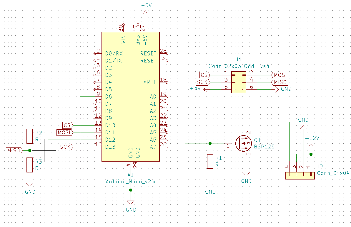
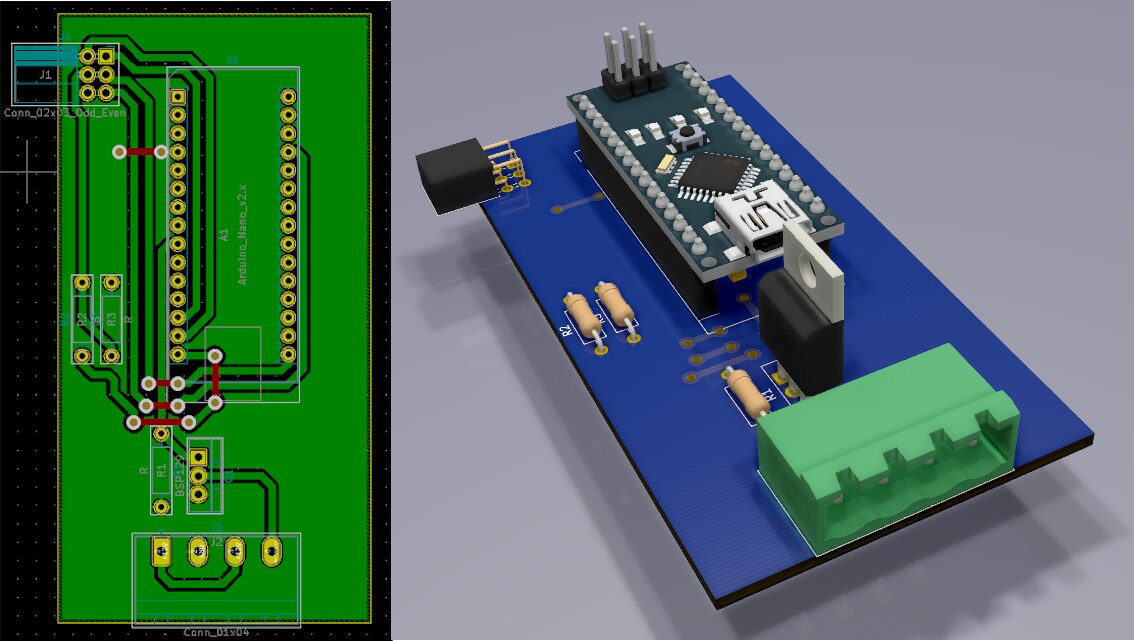
Output peripheral board
Similar to the input expansion card, the output card is equipped with Arduino Nano but this time it controls the NMOS transistor via PWM.
Housing
The housing of the project was made on a 3D printer. The main assumption was the possibility of placing the controller on a DIN rail (TH35) together with modular equipment. The housing was decided, just like the electronics, to be divided into 3 parts: input/output expansion card's housings and main board’s housing.
Electronics boards connected to the back of the housings:
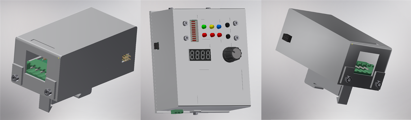
Separate housing designs:
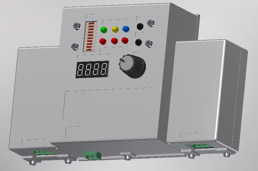
Complete housing with expansion cards connected:
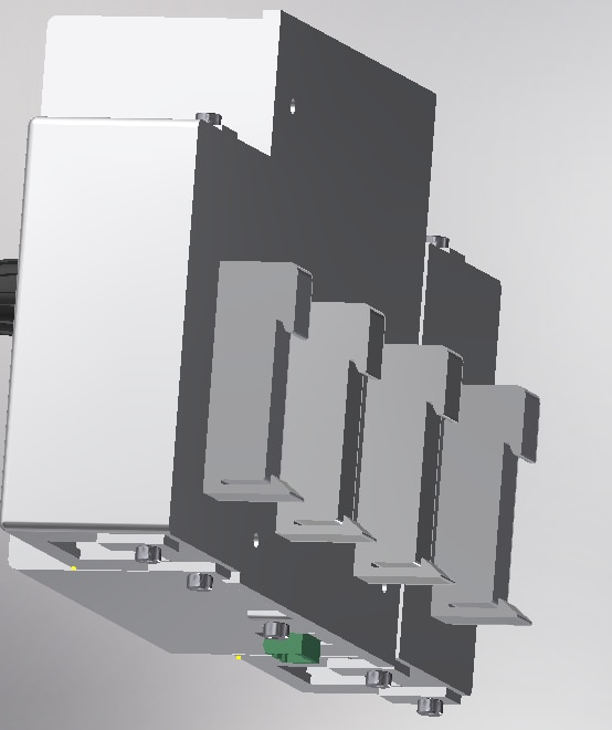
Back of the controller (DIN mounts created by https://www.thingiverse.com/RobertHunt/about (https://www.thingiverse.com/thing:101024)):
High level core
As described in General concepts, the main task of this core will be communication with virtual world. For this purpose, 2 timers were prepared that are responsible for periodical data transmission to MQTT and the Azure cloud. In addition, 2 callback functions were written that are responsible for receiving the setpoint value from MQTT topic and for GET request processing from HTTP server. In order to communicate with the real time core, the sample code from Azure’s repository was used (https://github.com/Azure/azure-sphere-samples/tree/master/Samples/IntercoreComms). Data transfer between cores is based on the master-slave principle, where the master is a high-level core that sends a frame containing the command and data. After frame has been sent from the master, it waits for a response from slave real time capable core. For simple commands, RT core responds with simple “ok”, in other cases it responds with data requested by high level core.
Web based configuration
In order to allow the user to configure the device, it was decided to provide a simple website at local_ip:8181/config. For this purpose a simple socket based HTTP server has been written which awaits in a separate thread for connections with clients:
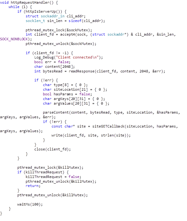
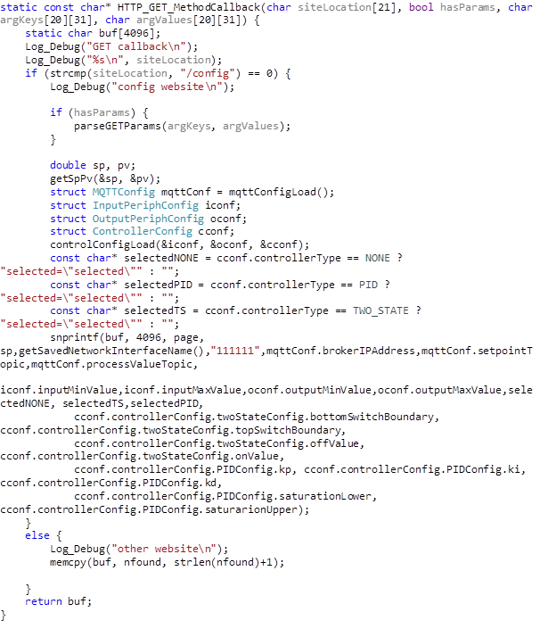
After connection, callback (siteGETCallback) is calles, in which, depending on the requested page’s location, the configuration website is provided, or a 404 error.
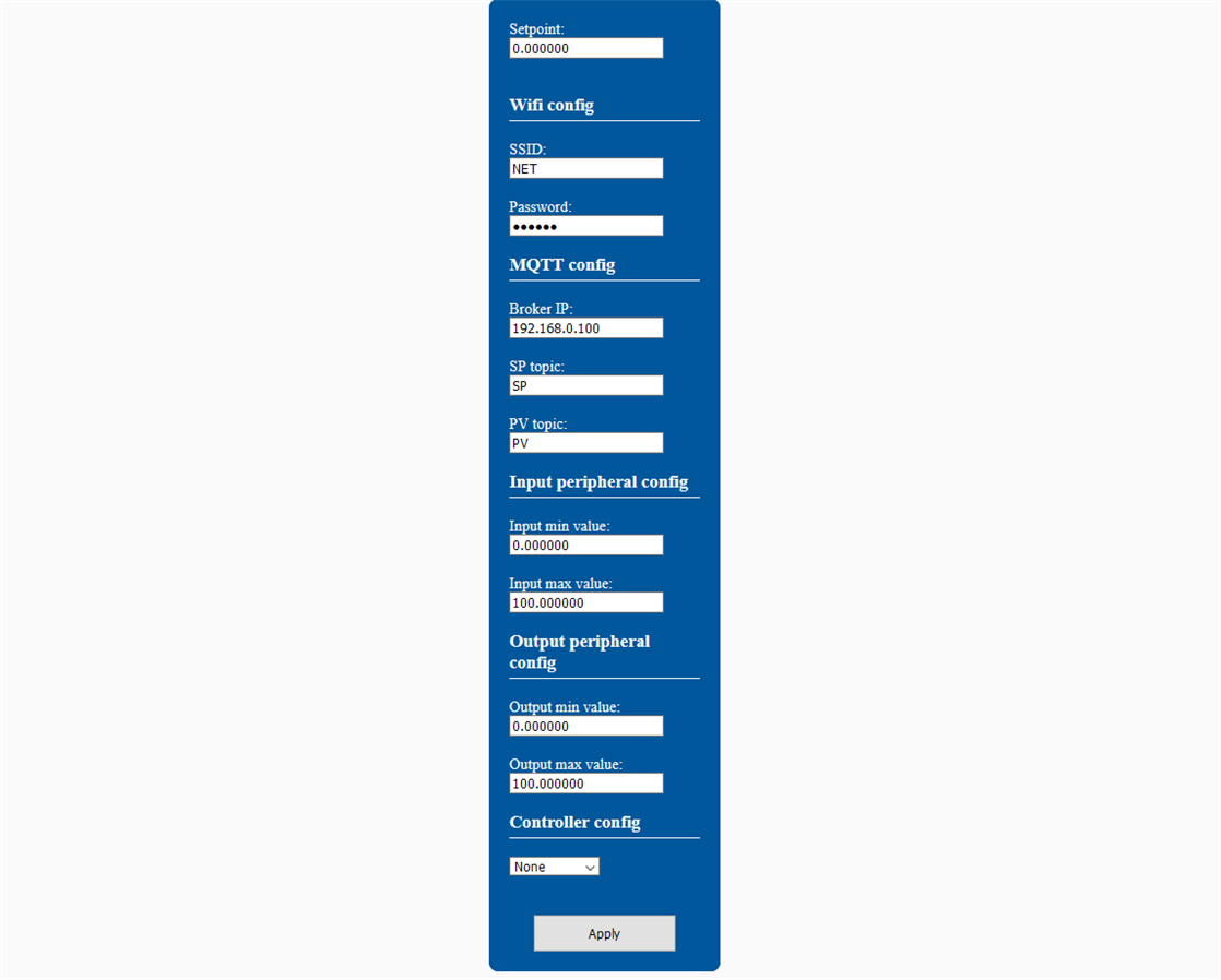
The configuration website is shown below:
Integration with home automation systems via MQTT
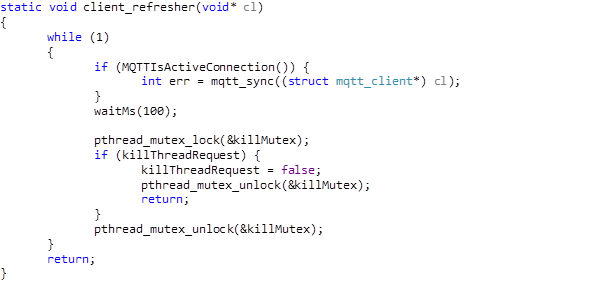
For communication with MQTT, a third party library was used (https://github.com/LiamBindle/MQTT-C) which works without any problems on Azure Sphere. To use this library, a wrapper header has been written to simplify the structure of the main code. As with HTTP server, the main MQTT loop runs on a separate thread:
And also has a callback that is called when a message is received from setpoint’s thread:

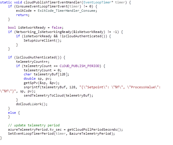
Cloud based control reporting
In the project, the cloud plays the role of supervisory panel in which current state of the control process can be seen. Every minute telemetry about current setpoint and process value is being sent to the cloud and both values are displayed on time plot.
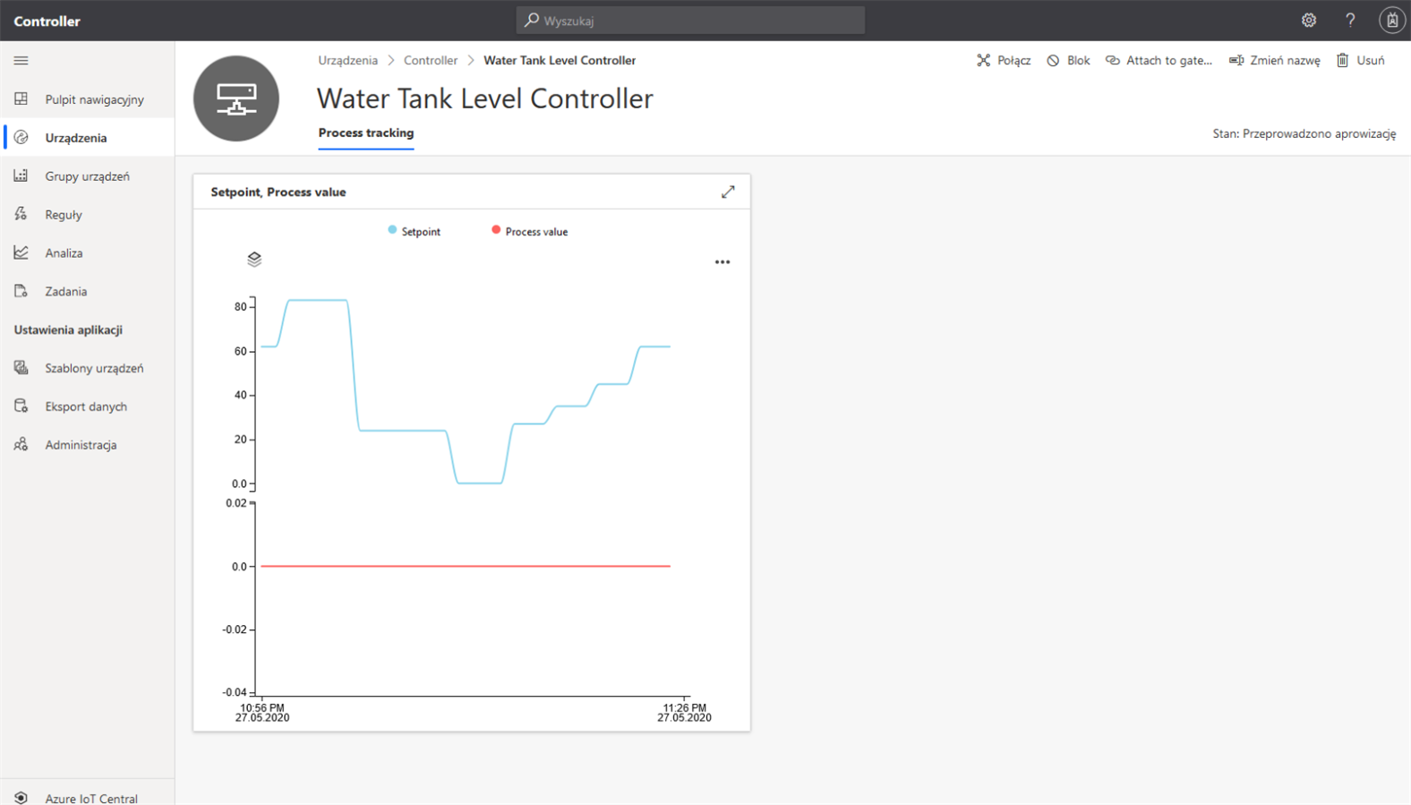
In the picture above, you can see setpoint changes made with knob over time. Input sensor was disconnected at the time so chart of process value is always 0.
Real time core
In order to control individual components of the real time core, it was decided to use the real time operating system (RTOS).
FreeRTOS
As the operatins system that manages all of GPIO communication, it was decided to use the well-known FreeRTOS. The use of a dedicated system will decompose individual task of the interface control and communication into simple and readable tasks. It will also provide time determinism required for PID control. the FreeRTOS version along with HAL library for Azure Sphere was obtained from: https://github.com/MediaTek-Labs/mt3620_m4_software.
UI Tasks
In order to control events from the operator panel, it was decided to use 4 tasks responsible for individual panel components:
- Button task – responsible for reacting on press events on the SP and IP buttons,
- Display task – responsible for displaying current setpoint, knob’s value or IP address depending on the global state of the RT core,
- LED task – responsible for controlling the led bar and LEDs signaling operation of the device,
- Knob task – responsible for reacting to a value change on the knob.
Communication with peripheral boards
It was decided to perform communication with the expansion cards through software SPI. While there is hardware SPI available on the board, it has been tested that for some reason it does not work with wifi and debug UART in use (this might be a defect in my board). The communication was decided to be divided into 2 algorithms: The first one that is used to read the input value, in which bytes of data and CRC are received. In the case of CRC error, the error counter is increased. When the counter reaches 10 errors in a row, the controller enters failure state. If the transaction is error free, then the counter is zeroed. Outputs are written in such way that a frame with CRC is sent to output expansion card and a byte with the result of the transaction is received in the next control cycle. In case when this byte is set to 1, the transaction was successful. In other cases, the transaction is considered erroneous and the error counter is increased. If the cards are disconnected from the controller, the transactions are automatically considered to be incorrect (due to incorrect CRC for inputs and incorrect transaction result byte for outputs).
Control algorithm task
A separate and the most important task from the project’s perspective is the task responsible for process control. In this task it was decided to use methodology known from PLCs in which the input is read first, then control algorithm is performed, then outputs are written. While it is possible to simultaneously read inputs and write outputs via SPI full duplex, it will introduce delays by sample for input or output card which is not a good solution from control engineering's perspective.
Mailbox task
Communication with high level core was decided to be obtained using separate task. This task executes all processes that have been assigned to the process queue by interrupts resulting from the incoming data provided by high level core.
External EEPROM memory
Communication with EEPROM memory is performed using I2C. Communication occurs at the request of one of the working tasks and is a synchronous procedure. The memory stores information about selected control algorithm, information about inputs/outputs and information about MQTT broker.
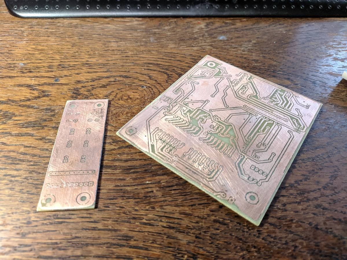
Realization of the board
Boards etched and ready to be drilled:
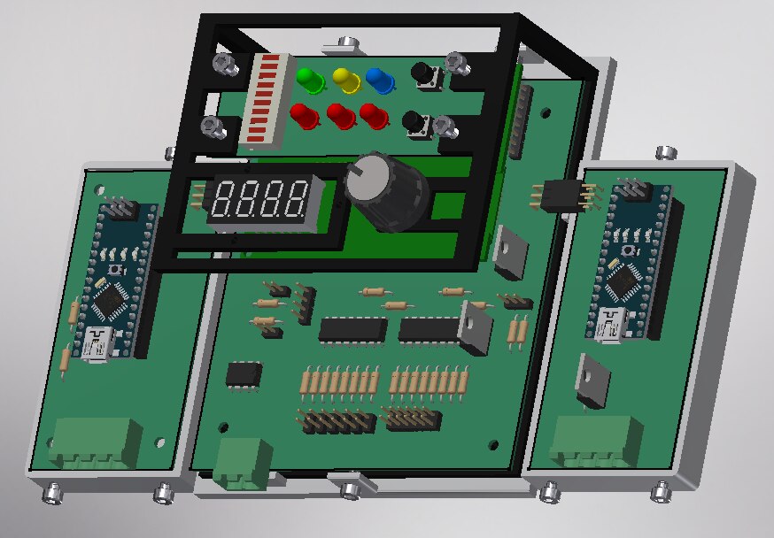
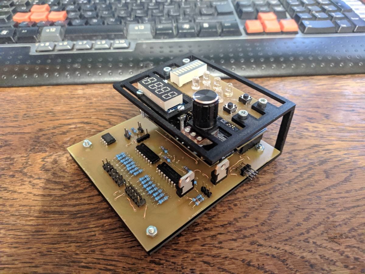
Main board with operator’s panel ready to be assembled:
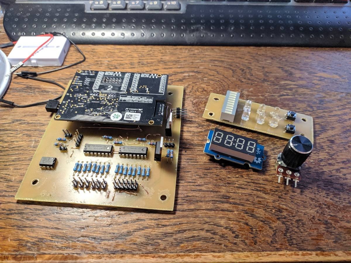
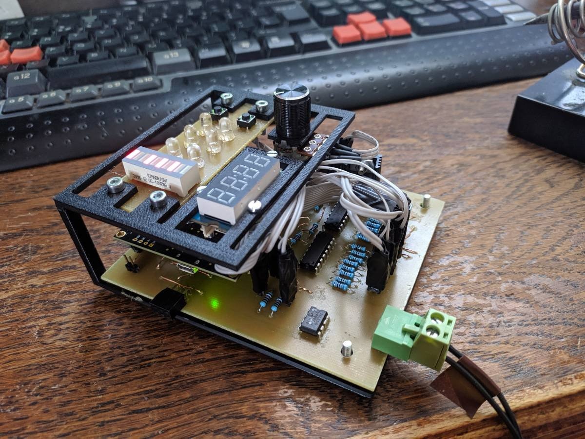
Assembled main board:
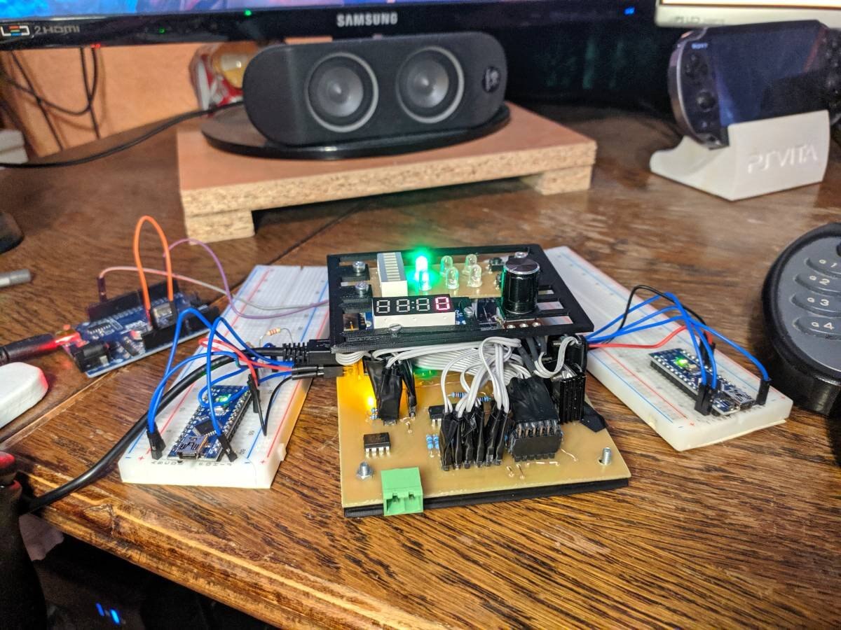
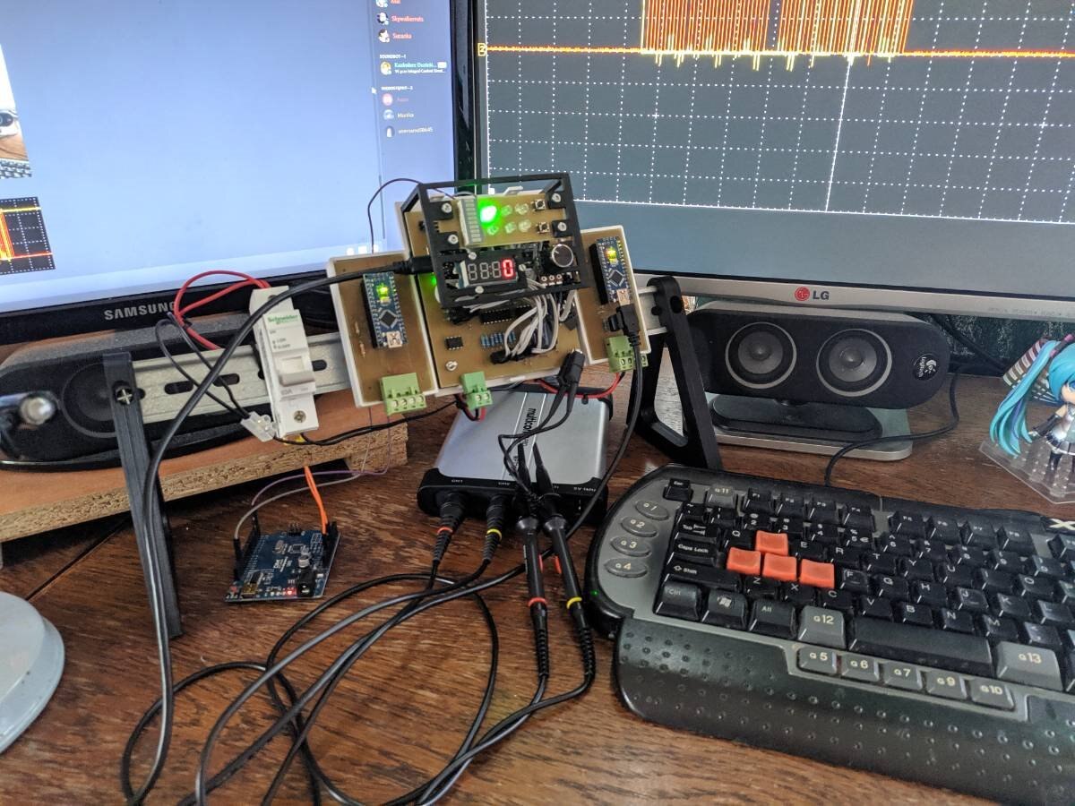
All the stuff connected and first test with external 12V voltage:
First tests of expansion cards on breadboards:
Expansion cards etched and soldered:
Complete electronic design on DIN rail, programming and bug fixing in progress:
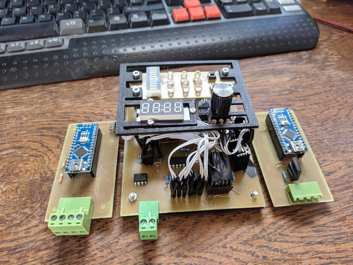
Completed controller:
Tests
Both tests were performed using MQTT script similar to script shown in one of the videos above. In the script setpoint's value is changed roughly every 7 minutes. The script changes the setpoint from 50 to 100 to 50 in increments of 15. Setpoint and process value were recorded using mosquitto MQTT broker.
Two state control
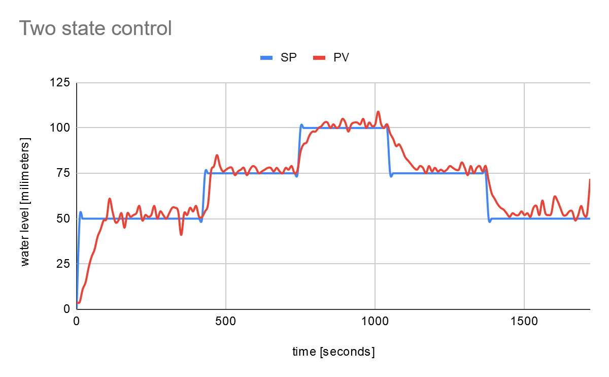
In the plot above you can see that two state control works and keeps value roughly around setpoint. But also you can see that the value oscillates around it (+/- 3 milimeters). This controller is ideal for slow processes or processes where some small error does not matter that much. In the project, following parameters were configured for two state controller:
- Max top error value: 2mm
- Max bottom error value: 2mm
- On value of the actuator: 12V
- Off value of the actuator: 0V
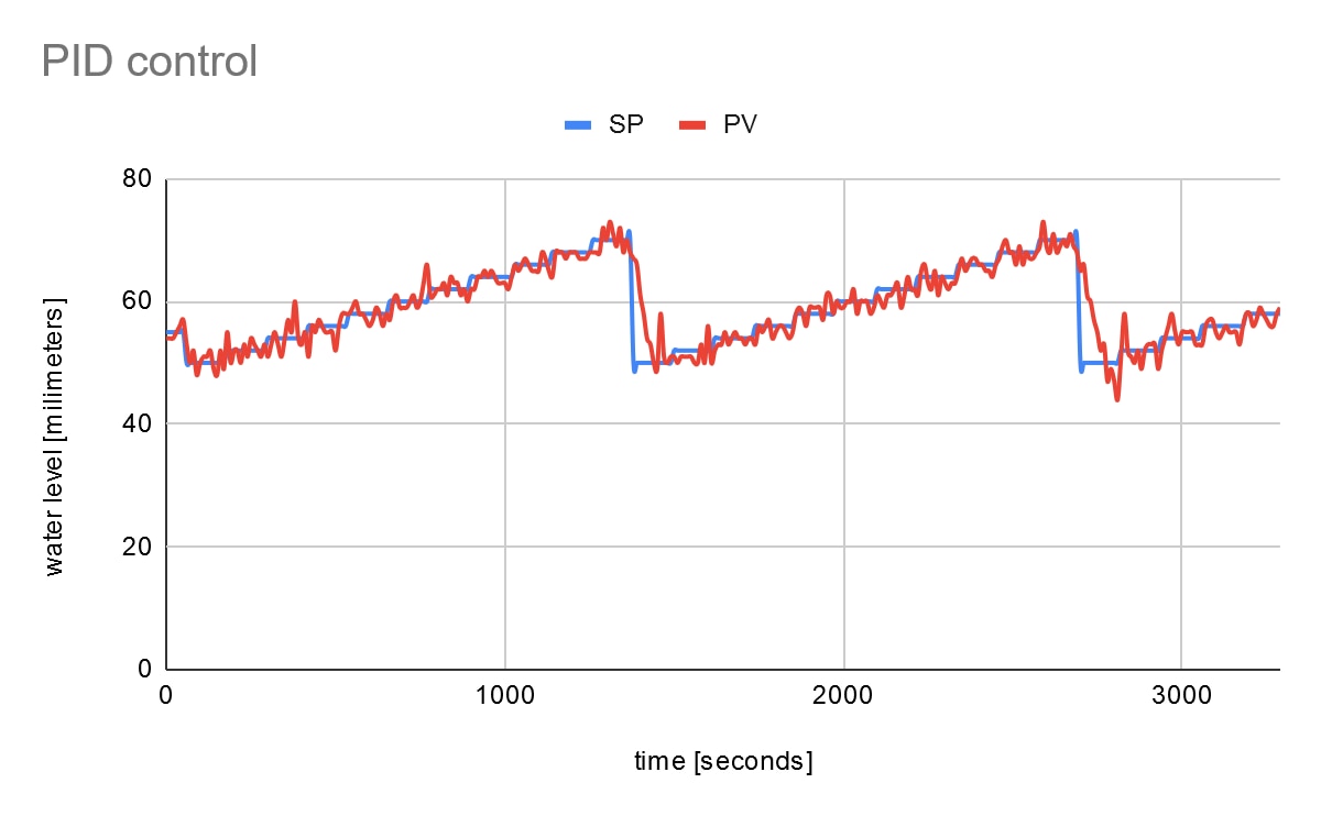
PID control

As you can see, PID control works a lot better than two state control. It keeps process value pretty much on setpoint's location. On the plot one problem can be seen: the sensor is a bit noisy and it can affect our control mechanism. In the project, following parameters were configured for PID controller controller:
- kp:20
- ki: 10
- kd: 0
- Lower CV saturation: 0
- Upper CV saturation: 12V
Longer test:
Bill of materials for main board
Electronics
- Avnet Azure Sphere board
- EEPROM 24LC01B-I/P24LC01B-I/P
- 74HC595 SIPO registers (2x)
- Led bar DC-10SRWA or similar
- TM1637 based 7 segment display with 4 segments (I have used Grove 7 segment module)
- Monostable tact switch buttons (most popular one) (2x)
- Blue clear led
- Yellow clear led
- Green clear led
- Red clear leds (3x)
- 10k linear potentiometer and knob
- 680Ohm resistors (12x)
- 220Ohm resistors (4x)
- 4.7k Ohm resistors (2x)
- 1k Ohm resistor
- 3.3k Ohm resistor
- 10k Ohm resistors (6x)
- L7805 voltage regulators and small radiators (2x)
- 3x1 2.54mm goldpin male and felame connectors
- 2x1 2.54mm goldpin male and female connectors (10x each)
- 4x1 2.54mm goldpin male and female connectors
- 6x2 2.54mm goldpin male and female connectors
- 6x2 2.54mm horizontal male and female connectors
- 2x1 5.00mm Phoenix MSTB connector
- Some cables for connections between main board and operator’s panel
- Some wire for jumpers
- Copper plate and stuff required for etching a board
Housing
- PLA filament
- Some M3 screws and nuts
Bill of materials for input board
Electronics
- Arduino Nano
- 1k Ohm resistor
- 2.2k Ohm resistor
- 6x2 2.54mm horizontal male connector
- 4x1 5.00mm Phoenix MSTB connector
Housing
- PLA filament
- Some M3 screws and nuts
Bill of materials for output board
Electronics
- Arduino Nano
- 1k Ohm resistor
- 2.2k Ohm resistor
- 10k Ohm resistor
- NFET transistor with pinout similar to 04N60C3 (I have used this because that’s the only NFET I had at the time) (Should be able to handle around 1Amp of load and have low enough GS threshold voltage so it can be controlled from Arduino)
- 6x2 2.54 horizontal female connector
Housing
- PLA filament
- Some M3 screws and nuts
Instructions how to recreate the controller
Electronics
- Simply etch the boards and solder all of the components based on provided schematics. Start with jumpers, then bigger elements.
- Solder female 2x1 connector into +5V header of Azure Sphere board
- Connect Azure Sphere board to the main board
- Solder some cables directly to the operator panel’s diodes, led bar and buttons and secure connections with hot glue (lazy way but ech)
- Connect operator’s panel to main board as in provided schematics
- Connect Arduino’s to already soldered expansion boards
- Connect expansion boards to main board
The code
- Prepare the board
- In azsphere shell add two networks to the board:
- azsphere dev wifi add –ssid AzCon –psk 12345678
- azsphere dev wifi add –ssid USER_NET –psk 12345678
- In azsphere shell add two networks to the board:
- Pull the code from project’s repository (requires git)
- Create some directory for the project
- Inside project’s directory in command line:
- git init
- git remote add origin https://github.com/Tai-Min/Azure-Sphere-Home-Process-Controller
- git pull origin master
- git submodule update –init –recursive
- Open the project in visual studio
- Upload RT Core
- Upload HL Core
- Download and insert following library inside Arduino’s "libraries" folder: https://github.com/Martinsos/arduino-lib-hc-sr04
- Change line in HCSR04.cpp from “unsigned long durationMicroSec = pulseIn(echoPin, HIGH);” to “unsigned long durationMicroSec = pulseIn(echoPin, HIGH, 30000);”
- Upload codes to expansion boards using Arduino IDE
- For Azure IoT Cental see: https://github.com/Azure/azure-sphere-samples/blob/master/Samples/AzureIoT/IoTCentral.md
- In Azure IoT Central, in Device Templates add new template, then new interface with “Setpoint” and “Process value” possibilities
- When you connect your device to a WiFi, in Azure IoT Central it should show under Devices, migrate device into your device template
Housing
- 3D print all stl files available in project’s repository with 0.2mm layer size , 20% infill and supports
- Assembly main board on adapter (black part on photos)
- 3D print DIN rail mounts (01 ver) from here: https://www.thingiverse.com/thing:101024
- Connect DIN mounts to the backs of the printed housings
- Connect boards to the back of the hounsings, main board via screws and nuts, expansion boards just clicks inside.
- Screw top parts of the housings via 3mm screws, no nuts needed
Top Comments