


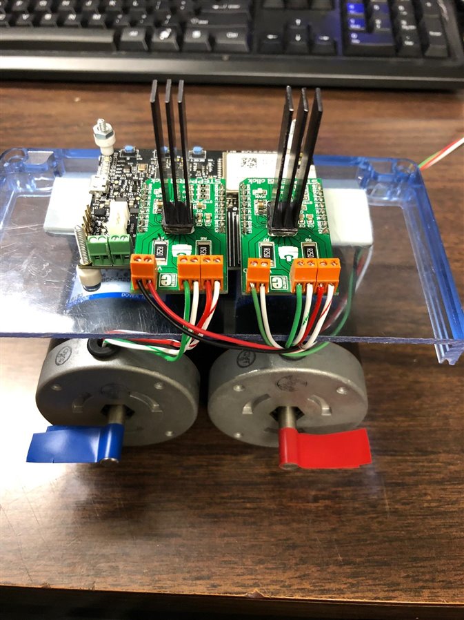
This project is a system to control and monitor a gated area in a vehicle lot or event space. The project is designed around the Avnet Azure Sphere MT3620 starter kit.

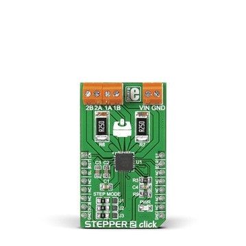
The system controls two gates or doorways. The gates are simulated using two stepper motors. The stepper motors are actuated using click stepper2 modules:
https://www.mikroe.com/stepper-2-click
The system waits for a request to open the incoming gate. The controller keeps a count of how many gate openings are actuated and in-out = how full. If the lot or event is full, the gate will not open and
a "Event Full" sign will illuminate. If the event is not full, then the stepper motor is actuated to let in the participant. The request to open the incoming gate is simulated by the "A" button on the Azure Sphere SK board.
The request to open the exit gate is simulated by the "B" button on the board. In a real situation, the input and exit gates could be actuated by a motion detector, a load cell or strain gage, or RFID/NFC card.
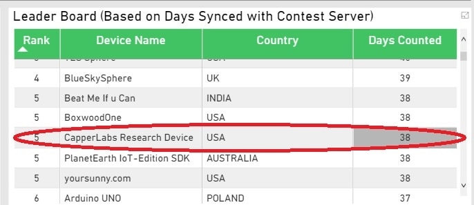
Phase 1 of the challenge is to ping the Azure Sphere server for at least 15 days,
I'm currently at 38.
The software is a modification of the Avnet demo software available on github.
AvnetAzureSphereStarterKitReferenceDesign-master
The first thing to do was to make the stepper motors turn. The libraries for the Click Stepper2 are not compatible with Visual Studio, so I had to write my own code.
The click stepper2 board uses 5 I/O pins.
- Enable,
- Reset,
- Direction,
- Chip Select,
- Step Input Pulse
To map the click board I/O, first look at the schematics for the boards:

Comparing this with the starter kit pin definitions from file mt3620_avnet_dev.h, these are the pin definitions for the first click module:
#define MIKROE_EN   AVT_MODULE_GPIO42_ADC1
#define MIKROE_RST  AVT_MODULE_GPIO16
#define MIKROE_DIR  AVT_MODULE_GPIO2_PWM2
#define MIKROE_CS   clickSocket1Relay1Fd
#define MIKROE_ST   clickSocket1Relay2Fd
static int step1PinFd;  //stepper2 #1
static GPIO_Value_Type step1Pin;
static int step2PinFd;  //stepper2 #2
static GPIO_Value_Type step2Pin;
static int step3PinFd;  //stepper2 #3
static GPIO_Value_Type step3Pin;
To initialize the first click module pins I set the enable, the reset, and the direction pins low:
void initMIKROE(void)
{
step1PinFd = GPIO_OpenAsOutput(MIKROE_EN, step1Pin, GPIO_Value_Low);
step2PinFd = GPIO_OpenAsOutput(MIKROE_RST, step2Pin, GPIO_Value_Low);
step3PinFd = GPIO_OpenAsOutput(MIKROE_DIR, step3Pin, GPIO_Value_Low);
}
When the open gate button is pressed, the first click module is enabled:
GPIO_SetValue(userLedRedFd, GPIO_Value_Low);
GPIO_SetValue(step1PinFd, GPIO_Value_Low);
GPIO_SetValue(step2PinFd, GPIO_Value_High);
GPIO_SetValue(step3PinFd, GPIO_Value_Low);
GPIO_SetValue(clickSocket1Relay1Fd, GPIO_Value_High);
GPIO_SetValue(clickSocket1Relay2Fd, GPIO_Value_High);
To cycle the motor the Step Input Pulse pin is toggled.
GPIO_SetValue(clickSocket1Relay2Fd, GPIO_Value_Low);
for (int index = 0; index < 100000; index++);
GPIO_SetValue(clickSocket1Relay2Fd, GPIO_Value_High);
for (int index2 = 0; index2 < 100000; index2++);
Connecting to the cloud:
I set up an account.

I configured an IotGroup and IoTHub
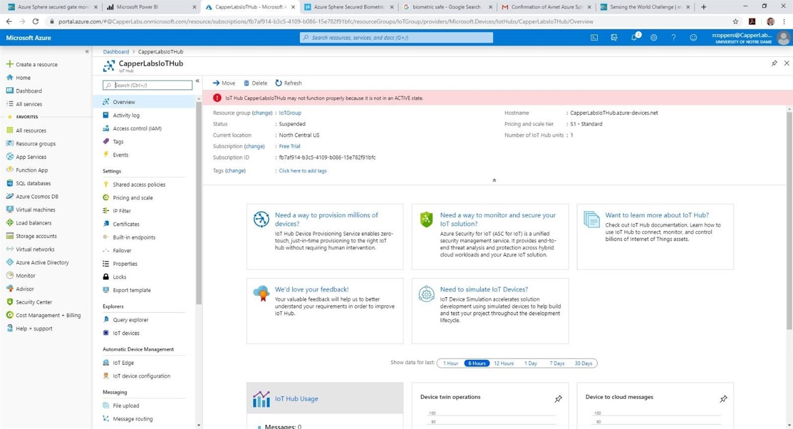
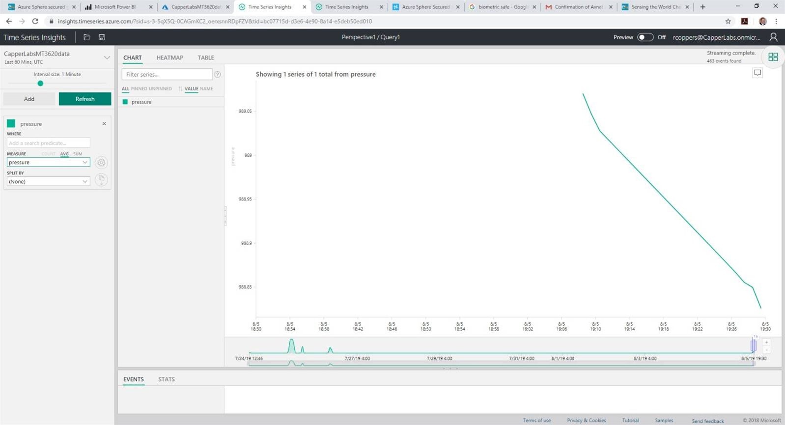
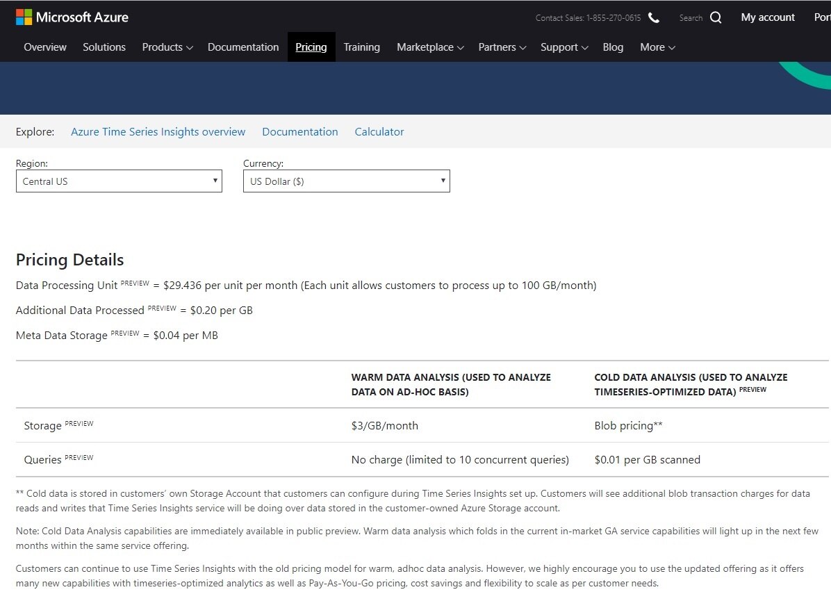
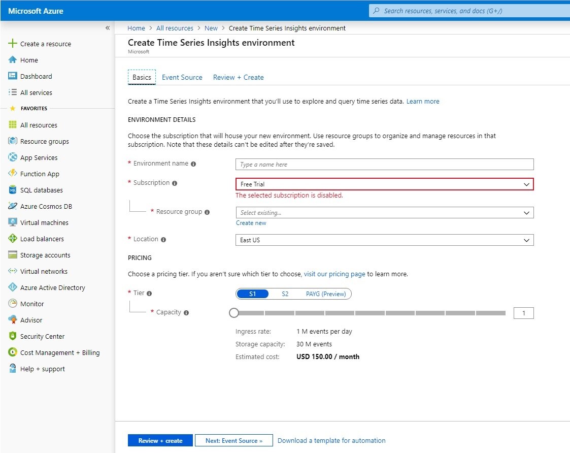
Then an IoT Time Series Insights page
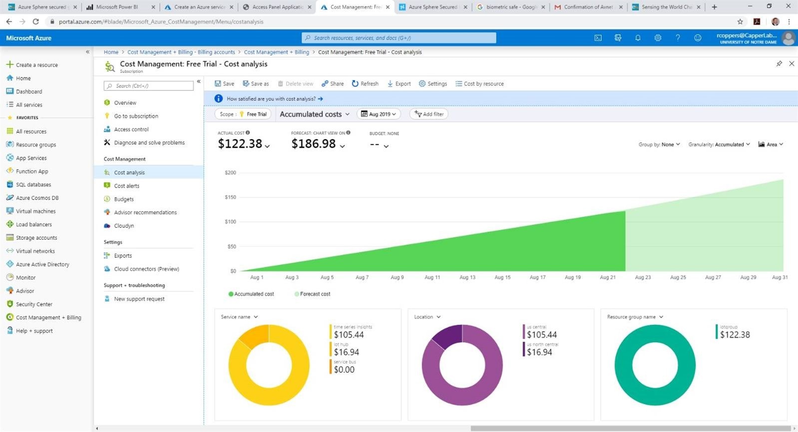
Then, after my free trial ended, deleted the time series page due to the cost.
Top Comments