element14 Community
element14 Community
    Register Log In
  • Site
  • Search
  • Log In Register
  • Community Hub
    Community Hub
    • What's New on element14
    • Feedback and Support
    • Benefits of Membership
    • Personal Blogs
    • Members Area
    • Achievement Levels
  • Learn
    Learn
    • Ask an Expert
    • eBooks
    • element14 presents
    • Learning Center
    • Tech Spotlight
    • STEM Academy
    • Webinars, Training and Events
    • Learning Groups
  • Technologies
    Technologies
    • 3D Printing
    • FPGA
    • Industrial Automation
    • Internet of Things
    • Power & Energy
    • Sensors
    • Technology Groups
  • Challenges & Projects
    Challenges & Projects
    • Design Challenges
    • element14 presents Projects
    • Project14
    • Arduino Projects
    • Raspberry Pi Projects
    • Project Groups
  • Products
    Products
    • Arduino
    • Avnet Boards Community
    • Dev Tools
    • Manufacturers
    • Multicomp Pro
    • Product Groups
    • Raspberry Pi
    • RoadTests & Reviews
  • About Us
  • Store
    Store
    • Visit Your Store
    • Choose another store...
      • Europe
      •  Austria (German)
      •  Belgium (Dutch, French)
      •  Bulgaria (Bulgarian)
      •  Czech Republic (Czech)
      •  Denmark (Danish)
      •  Estonia (Estonian)
      •  Finland (Finnish)
      •  France (French)
      •  Germany (German)
      •  Hungary (Hungarian)
      •  Ireland
      •  Israel
      •  Italy (Italian)
      •  Latvia (Latvian)
      •  
      •  Lithuania (Lithuanian)
      •  Netherlands (Dutch)
      •  Norway (Norwegian)
      •  Poland (Polish)
      •  Portugal (Portuguese)
      •  Romania (Romanian)
      •  Russia (Russian)
      •  Slovakia (Slovak)
      •  Slovenia (Slovenian)
      •  Spain (Spanish)
      •  Sweden (Swedish)
      •  Switzerland(German, French)
      •  Turkey (Turkish)
      •  United Kingdom
      • Asia Pacific
      •  Australia
      •  China
      •  Hong Kong
      •  India
      •  Korea (Korean)
      •  Malaysia
      •  New Zealand
      •  Philippines
      •  Singapore
      •  Taiwan
      •  Thailand (Thai)
      • Americas
      •  Brazil (Portuguese)
      •  Canada
      •  Mexico (Spanish)
      •  United States
      Can't find the country/region you're looking for? Visit our export site or find a local distributor.
  • Translate
  • Profile
  • Settings
Dev Tools
  • Products
  • More
Dev Tools
Forum Transistor selection on LED project, clever switch
  • Forum
  • Documents
  • Files
  • Members
  • Mentions
  • Sub-Groups
  • Tags
  • More
  • Cancel
  • New
Join Dev Tools to participate - click to join for free!
Actions
  • Share
  • More
  • Cancel
Forum Thread Details
  • Replies 8 replies
  • Subscribers 81 subscribers
  • Views 1060 views
  • Users 0 members are here
  • transistor
  • embedded
  • development
Related

Transistor selection on LED project, clever switch

Catwell
Catwell over 14 years ago
image
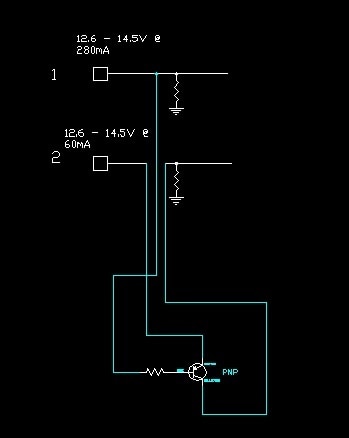
I have an issue; I need to turn off one LED if the other is on. The power is coming from the Pins labeled 1 & 2 in the diagram. The solution I want to use is a transistor placed on pin 2 that will pull it to ground when pin 1 activates the base.
 
 
Based on the voltage and current conditions, can anyone recommend a transistor and resistor for my solution?
 
 
Thanks in advance.
 
 
Cabe
  • Sign in to reply
  • Cancel
Parents
  • Jorge_Garcia
    Jorge_Garcia over 14 years ago

    For your pull downs I would suggest 10k that is a common value and won't draw much current away from the LEDs (1.26mA). Many small signal transistors have an hFe around 100 so if you want your E-C current to be about 60mA then you should select the resistor that will sink about 0.6mA from the base. To allow for some margin(and to make easy calculations). I'll design the resistor to sink 1mA.


    In the lowest sink case the voltage at your emitter will be 12.6V, assuming a Vbe drop of 0.7V(fairly standard) the put the base voltage at 11.9V base resistor is pulled to ground we want it to sink only 1mA so using ohm's law 11.9V/1mA= 11.9k resistor.


    The nearest standard value is 10k. If we use that in our calculations the base current at 12.6V supply is 1.19mA, with 14.5V it goes up to 1.38mA which is fine.


    So I recommend you use 10k resistors all around.


    For the transistor I recommend you use the ubiquious 2N3906 PNP Transistor, its cheap and available from a bunch of manufacturers, The currents your manipulating are well within the limits of the transistor.


    Since the transistor is being used as a switch the power dissipated can be calculated by multiplying the current time the Vce saturation voltage. Punching the numbers comes out to 30mW of power dissipated which if multiply time the junction to ambient thermal resistance(200C/W) gives a temperature rise of 6C above ambient which is not a big deal.


    So to recap use


    10k 1/4W resistors all around

    2N3906 PNP transistor


    hth,


    Jorge Garcia

    • Cancel
    • Vote Up 0 Vote Down
    • Sign in to reply
    • Cancel
  • Catwell
    Catwell over 14 years ago in reply to Jorge_Garcia

    Jorge,

    I ended up going with a BXC69 PNP Transistor, 20V, and a 2.5K resistor. But as you said, a 10K would have worked too.


    Thank you for the help!

    Cabe

    • Cancel
    • Vote Up 0 Vote Down
    • Sign in to reply
    • Cancel
  • Jorge_Garcia
    Jorge_Garcia over 14 years ago in reply to Catwell

    Sounds good Cabe,


    I generally don't give a 300% power margin so  I see where you are concerned. I have a small disagreement with your assertion that you will be dissipation 14.5V*60mA in the transistor. If that were the case than the colector of your PNP transistor should be to ground and you would basically be burning power for no reason. I used the saturation value Vce value to calculate the power dissipated across the transistor.


    The calculation should be as follows:


    14.5*60ma=0.87W Total Power

    -0.5V*60mA=0.06W Dissipated in the transistor


    The remaining 0.81W should be consumed by the load which are the LEDs in your case. Takes some measurements of your circuit and see what you get, the idea behind using the transistor as a switch is to disspate a small amount of power across the transistor so that most of the available power can make it to the LED.


    I'm glad your circuit is working, and nothing of what I mentioned here would affect your current circuit, but I thought it would be good to mention.


    What do you think, does my argument makes sense?

    • Cancel
    • Vote Up 0 Vote Down
    • Sign in to reply
    • Cancel
Reply
  • Jorge_Garcia
    Jorge_Garcia over 14 years ago in reply to Catwell

    Sounds good Cabe,


    I generally don't give a 300% power margin so  I see where you are concerned. I have a small disagreement with your assertion that you will be dissipation 14.5V*60mA in the transistor. If that were the case than the colector of your PNP transistor should be to ground and you would basically be burning power for no reason. I used the saturation value Vce value to calculate the power dissipated across the transistor.


    The calculation should be as follows:


    14.5*60ma=0.87W Total Power

    -0.5V*60mA=0.06W Dissipated in the transistor


    The remaining 0.81W should be consumed by the load which are the LEDs in your case. Takes some measurements of your circuit and see what you get, the idea behind using the transistor as a switch is to disspate a small amount of power across the transistor so that most of the available power can make it to the LED.


    I'm glad your circuit is working, and nothing of what I mentioned here would affect your current circuit, but I thought it would be good to mention.


    What do you think, does my argument makes sense?

    • Cancel
    • Vote Up 0 Vote Down
    • Sign in to reply
    • Cancel
Children
  • JohnDSiviter
    JohnDSiviter over 14 years ago in reply to Jorge_Garcia

    I would just use a cmos quad not gate IC, or program a simple pic10f for simple switching: http://uk.farnell.com/microchip/pic10f220t-i-mc/8bit-flash-mcu-smd-10f220-dfn-6/dp/1332174, leave transistors for analogue tasks image (unless you really must operate from those supply rails).

    • Cancel
    • Vote Up 0 Vote Down
    • Sign in to reply
    • Cancel
  • Former Member
    Former Member over 14 years ago in reply to JohnDSiviter

    In the case if you dont have a regultade 3,3 or 5 V i have used PIC12HV615 sometimes - just a resistor and then you have the power to the MCU without any expensive LDO regulators - oki, not the best solution when it comes to save energy, but careful setting of the shunt resistor makes it oki in lots of applications like fancontroll (i have used it as a smart temperature controlling buch converter regulator with the PWM module). Few and cheap components - workes well! The 10F204 is also a nice component that io have build a PWM generator with a two button controllinterface with - it is good stuff and keeps down the lenght of the BOM.

    • Cancel
    • Vote Up 0 Vote Down
    • Sign in to reply
    • Cancel
  • Catwell
    Catwell over 14 years ago in reply to Former Member

    Bengt,


    Thank you for the suggestion. I would have prefered to go the MCU route, but the PCB area was less that 1.5cm x 1.5cm. I could only place components on one side.


    I posted the final design I used. I did the whole circuit with 2 mosfets, as opposed to a microcontroller and power handling components. The main issue I had was with the extremely low forward voltage of the LEDs. With the new design, I was able to drop the voltage on the line to almost zero.


    Cabe

    • Cancel
    • Vote Up 0 Vote Down
    • Sign in to reply
    • Cancel
element14 Community

element14 is the first online community specifically for engineers. Connect with your peers and get expert answers to your questions.

  • Members
  • Learn
  • Technologies
  • Challenges & Projects
  • Products
  • Store
  • About Us
  • Feedback & Support
  • FAQs
  • Terms of Use
  • Privacy Policy
  • Legal and Copyright Notices
  • Sitemap
  • Cookies

An Avnet Company © 2025 Premier Farnell Limited. All Rights Reserved.

Premier Farnell Ltd, registered in England and Wales (no 00876412), registered office: Farnell House, Forge Lane, Leeds LS12 2NE.

ICP 备案号 10220084.

Follow element14

  • X
  • Facebook
  • linkedin
  • YouTube