element14 Community
element14 Community
    Register Log In
  • Site
  • Search
  • Log In Register
  • About Us
  • Community Hub
    Community Hub
    • What's New on element14
    • Feedback and Support
    • Benefits of Membership
    • Personal Blogs
    • Members Area
    • Achievement Levels
  • Learn
    Learn
    • Ask an Expert
    • eBooks
    • element14 presents
    • Learning Center
    • Tech Spotlight
    • STEM Academy
    • Webinars, Training and Events
    • Learning Groups
  • Technologies
    Technologies
    • 3D Printing
    • FPGA
    • Industrial Automation
    • Internet of Things
    • Power & Energy
    • Sensors
    • Technology Groups
  • Challenges & Projects
    Challenges & Projects
    • Design Challenges
    • element14 presents Projects
    • Project14
    • Arduino Projects
    • Raspberry Pi Projects
    • Project Groups
  • Products
    Products
    • Arduino
    • Avnet Boards Community
    • Dev Tools
    • Manufacturers
    • Multicomp Pro
    • Product Groups
    • Raspberry Pi
    • RoadTests & Reviews
  • Store
    Store
    • Visit Your Store
    • Choose another store...
      • Europe
      •  Austria (German)
      •  Belgium (Dutch, French)
      •  Bulgaria (Bulgarian)
      •  Czech Republic (Czech)
      •  Denmark (Danish)
      •  Estonia (Estonian)
      •  Finland (Finnish)
      •  France (French)
      •  Germany (German)
      •  Hungary (Hungarian)
      •  Ireland
      •  Israel
      •  Italy (Italian)
      •  Latvia (Latvian)
      •  
      •  Lithuania (Lithuanian)
      •  Netherlands (Dutch)
      •  Norway (Norwegian)
      •  Poland (Polish)
      •  Portugal (Portuguese)
      •  Romania (Romanian)
      •  Russia (Russian)
      •  Slovakia (Slovak)
      •  Slovenia (Slovenian)
      •  Spain (Spanish)
      •  Sweden (Swedish)
      •  Switzerland(German, French)
      •  Turkey (Turkish)
      •  United Kingdom
      • Asia Pacific
      •  Australia
      •  China
      •  Hong Kong
      •  India
      •  Korea (Korean)
      •  Malaysia
      •  New Zealand
      •  Philippines
      •  Singapore
      •  Taiwan
      •  Thailand (Thai)
      • Americas
      •  Brazil (Portuguese)
      •  Canada
      •  Mexico (Spanish)
      •  United States
      Can't find the country/region you're looking for? Visit our export site or find a local distributor.
  • Translate
  • Profile
  • Settings
Dev Tools
  • Products
  • More
Dev Tools
Forum Power protection on PSoC with regulated VCC
  • Forum
  • Documents
  • Files
  • Members
  • Mentions
  • Sub-Groups
  • Tags
  • More
  • Cancel
  • New
Join Dev Tools to participate - click to join for free!
Actions
  • Share
  • More
  • Cancel
Forum Thread Details
  • State Verified Answer
  • Replies 9 replies
  • Answers 2 answers
  • Subscribers 77 subscribers
  • Views 1310 views
  • Users 0 members are here
  • l298
  • diode
  • gearbest controller board
  • power protection
  • psoc 4200 family
  • stepper
  • zener diode
  • cypress
  • motor controller
  • psoc
Related

Power protection on PSoC with regulated VCC

balearicdynamics
balearicdynamics over 8 years ago

Below the entire circuit I refer to (it will be part of an article as this last detail I will explain below is clear to me.

image

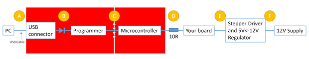
This is the schematics for a dual stepper motor controller. The PSoC 4200 series controls a couple of stepper motors through two GearBest Motor controller boards and it works fine. The 5VCC power for the PSoC is got from the extra 5VCC regulated power pin on the board while the GND is common. What I see is that in the final 5VCC power line from the board there is no diode protection; this is +5 VCC out when the board is powered (12VCC, 2A) but if I power off the board leaving the cables connected to the PSoC and the PSoC is powered through the USB connector, it tries (unsuccessfully) to power the board and the USB on the computer become unstable.

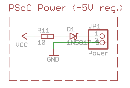
This experimental verification suggest me to put a zener diode between VCC and GND (the PSoC Power (+5V reg.) block in the design). What value do you suggest ? Or this is totally wrong?


Take in account that in theory the USB connection should not be used for normal production but for programming only but it is also possible that after the assembly the normal power line is not so easy to remove while for some reasons the PSoC should be reprogrammed via the USB.


thank in advance. Enrico

  • Sign in to reply
  • Cancel

Top Replies

  • rachaelp
    rachaelp over 8 years ago +2
    Hi Enrico, I don't think using a zener between VCC and GND will achieve what you want it to achieve. I'd suggest you need your VCC external input to the PSoC to be supplied through a diode with low Vf…
  • balearicdynamics
    balearicdynamics over 8 years ago in reply to rachaelp +2
    Thank you Rachel! you are addressing me on the right way despite the low level of caffeine your grey cells seems working almost fine Enrico
  • shabaz
    shabaz over 8 years ago in reply to balearicdynamics +2 suggested
    Hi Enrico, I drew the sketch below to show my current understanding, I'm not sure if I've completely understood it or not. Does it look correct? I've labelled all the potential areas where things could…
Parents
  • shabaz
    0 shabaz over 8 years ago

    Hi Enrico,

    It is an interesting question, because it would apply to many scenarios where people want to use the Cypress board.

    I think there are a couple of things that could be done simultaneously, one is that a diode would be good to protect the PC in case the 12V-derived 5V supply is too high, and looking at the PSoC board, there are a couple of places it could be fitted; one is to cut the VCC connection at the snap-off portion and place the diode in series there, or another way is to remove the fuse F1 on the board and replace it with a diode. This ON-Semi MBRM110L diodeON-Semi MBRM110L diode should fit, and has very low Vf so hopefully it should have no negative impact.

    This way the PC (through the USB connection) will not accidentally be supplied with 5V derived from the 12V source.

    The other issue as you say is that if your 12V-derived 5V supply is powered off, then the PC (through the USB) could end up powering some unexpected circuitry. Maybe a quick fix is to place a small resistance (e.g. 10 ohm) in the 5V supply line from the PSoC board, e.g. at SV1 pin 1 in your schematic, so that the amount of current that can be supplied from the PC USB connection is limited. With the PC USB disconnected, the 10 ohms will still allow the PSoC board to be powered from the 12V-derived source because the PSoC board consumes little current.

    What do you think?

    • Cancel
    • Vote Up +1 Vote Down
    • Sign in to reply
    • Reject Answer
    • Cancel
  • balearicdynamics
    0 balearicdynamics over 8 years ago in reply to shabaz

    Hello Shabaz, thank you for your precious suggestions and the very complete explanation.


    Respect the first part of your post, you say

    one is that a diode would be good to protect the PC in case the 12V-derived 5V supply is too high, and looking at the PSoC board, there are a couple of places it could be fitted; one is to cut the VCC connection at the snap-off portion and place the diode in series there, or another way is to remove the fuse F1 on the board and replace it with a diode. This ON-Semi MBRM110L diode should fit, and has very low Vf so hopefully it should have no negative impact.

    I will adopt the first option for two reasons; the first is that it is almost easy to implement without changing too much the schematics. But the most important thing is that as an external circuit will exist for sure I think it is more clear to complete the circuitry around the PSoC 4200 kit instead of changing it; I plan to setup about 50 of these boards and it is better to put the small kit in place instead of replicating the same fuse replacement to all the devices. There is also the consideration that if in future this small dedicated production will become a sort of product for some reason the PSoC kit will be replaced by the bare chip with the minimal electronics around it just to support this particular features (with a meaningful reduction of the entire board size).


    About the limiting resistor it sounds also a good yet simple solution. Also considering that there is not a real damage but the USB programmer wont work at all. If I am not wrong the resulting power terminal should be something like the image below.


    Enrico


    image

    • Cancel
    • Vote Up 0 Vote Down
    • Sign in to reply
    • Verify Answer
    • Cancel
  • shabaz
    0 shabaz over 8 years ago in reply to balearicdynamics

    Hi Enrico,


    I drew the sketch below to show my current understanding, I'm not sure if I've completely understood it or not.

    Does it look correct?

    I've labelled all the potential areas where things could be modified with the letters A, B, C...F.

    Regarding the resistor, I think it has to go at point D or E preferably (or points A, B or C less preferably), this way any power from the PC does not end up supplying the Stepper Driver board or any other circuitry attached in that area, because it will only provide limited current. As a result the PC should not become unstable.

    image

    For the diode, this is just an idea to prevent the 12V supply generated 5V from sending power to the PC by accident. If the diode (shown at position B in the diagram) is in position A,B or C, then when both the PC USB is connected and the 12V supply is connected, there is no risk of the PC getting damaged by the 12V supply generated 5V. If the diode was in position D or E or F then with the orientation as shown (i.e. Anode on the left) in my diagram, it would not be possible for the 12V generated 5V supply to power the microcontroller, so this would not be good. With the diode rotated 180 degrees (anode on the right), then it would work for any position A,B,C,D or E, I think it is a good idea, it will reduce the supply slightly and hopefully therefore not damage the PC USB port, although the protection is less than the anode-on-the-left confiigurations which have the limitation that they can only be placed at A,B or C.

    So, in summary, I think diode and resistor can be at the same location (i.e. position D or E) with the anode-on-right.

    • Cancel
    • Vote Up +2 Vote Down
    • Sign in to reply
    • Verify Answer
    • Reject Answer
    • Cancel
  • balearicdynamics
    0 balearicdynamics over 8 years ago in reply to shabaz

    Hello Shabaz, what was not 100% clear was the presence of the diode, you mean in series to the USB. So it is not correct in my previous design but it is useless in the usage context of this circuit. The only real problem is when the USB is connected to the kit, it tries to power the board, if by accident you have not disconnected the point D. So this will be solved by the resistor.

    The opposite will never happen because when the stepper driver controller is engage there can't be any PC to USB connected at all.


    Enrico

    • Cancel
    • Vote Up +2 Vote Down
    • Sign in to reply
    • Verify Answer
    • Cancel
  • shabaz
    0 shabaz over 8 years ago in reply to balearicdynamics

    Hi Enrico,


    Ah, I see! Perfect. In that case just the resistor is sufficient I agree.

    • Cancel
    • Vote Up +2 Vote Down
    • Sign in to reply
    • Verify Answer
    • Reject Answer
    • Cancel
Reply
  • shabaz
    0 shabaz over 8 years ago in reply to balearicdynamics

    Hi Enrico,


    Ah, I see! Perfect. In that case just the resistor is sufficient I agree.

    • Cancel
    • Vote Up +2 Vote Down
    • Sign in to reply
    • Verify Answer
    • Reject Answer
    • Cancel
Children
No Data
element14 Community

element14 is the first online community specifically for engineers. Connect with your peers and get expert answers to your questions.

  • Members
  • Learn
  • Technologies
  • Challenges & Projects
  • Products
  • Store
  • About Us
  • Feedback & Support
  • FAQs
  • Terms of Use
  • Privacy Policy
  • Legal and Copyright Notices
  • Sitemap
  • Cookies

An Avnet Company © 2025 Premier Farnell Limited. All Rights Reserved.

Premier Farnell Ltd, registered in England and Wales (no 00876412), registered office: Farnell House, Forge Lane, Leeds LS12 2NE.

ICP 备案号 10220084.

Follow element14

  • X
  • Facebook
  • linkedin
  • YouTube