


Hello Everyone,
I sat down last night and was trying to figure out the mathematics on burning text
to discs in different sizes based on 8x8 and 16x16 pixel character sizes, but once I
got started, I kept increasing the pixel size per char to get an idea on how things might
look on a finished burn.
The concept is fairly simple and easy to understand:

Here is what I had in mind in creating a disc:
1. Create a pixel map of x amount of chars per character line for the entire disc
2. Buffer the entire disc data before burning, (1Mbit Microchip SPI SRAM)
3. Start motor at proper revolutions per second for the bitrate per rev.
4. Place square wave on SPI SRAM clock line to clock out data to the laser.
A sample image showing an estimated output with text, and barcodes for the inner and outer BCA cutting area:

Chart Suitable for CD-RW laser - Low Res:
Based on 1 revolution per second for easy testing during development:
16384 pixel scan-lines: 8x8px chars and multiples of 8x8 to keep 1:1 ratio

Chart Suitable for DVD-RW laser - Medium Res:
Based on 1 revolution per second for easy testing during development:
131072 pixel scan-lines: 8x8px chars and multiples of 8x8 to keep 1:1 ratio
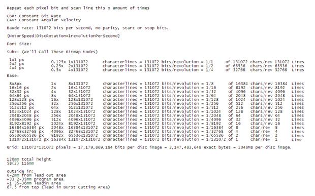
Note that a bitmap mode is possible, allowing users to freelance and set bits manually or import 1 bit artwork, and maybe even gray-scale if I can tune the laser correctly. Higher resolutions than this can use a BD-RE laser. The reason for the different types might be from the dots per revolution, using the appropriate laser for the resolution would make the graphics look as good as possible.
We'll implement a couple digital to analog converters in hardware with R2R Dacs and use
AND gates to trigger output to the motors and the laser with appropriate voltage so we
don't burn out components.
Creating a Font isn't that hard.. Here's one I put together this morning:
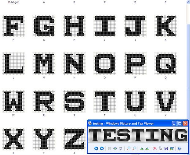
While designing your font, it would make sense to create 4:3 and 16:9 ratio versions of the fontset though aspect ratio is mostly seen in NTSC, PAL or 1080/2160 Video. This could be implemented in a PC program that will talk with our circuit, possibly telling the Arduino which font variation to use per font set. We'll be bringing video standards into this Arduino based laser printer project:

The way I have pixel layout figured, we can go to new lines without disrupting any laser beam because the way the font is designed, all sides of each char have 1px blank spacing with the char centered. This means the laser can move to a new pixel line without even being on due from a previous pixel being 0x00 from a previous line, this provides a grace period:
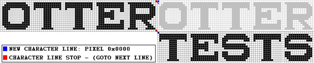
Since we'll be burning in a circular motion, the beginning of the next new character line is only 1 pixel away from the end of the previous line, so no carriage return or laser beam y+8 or y+16 is needed, unless you're wanting to implement a real time processing typewriter.
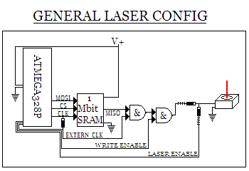
Here's a basic laser controller that might work for the laser, but I'd be running it through some resister network like an 8-bit DAC in hardware. Based on this, the pull-up resister would keep the laser on and fire high through an AND gate though another AND gate could be placed before that pull-up resister so the laser only turned on when ANDed with a MCU pin.
This guide might help aid in making the images look as good as possible
Smaller dots doesn't always mean better graphics, especially with CAV:
Use a CD-RW Laser for 16,384 bits/pixels per revolution
Use a DVD-RW Laser for 131,072 bits/pixels per revolution
Use a BD-RE Laser for 1,048,576 bits/pixels per revolution
Use a 4K-UHD-RE Laser for 8,388,608 bits/pixels per revolution
Perhaps we could even create our own circuit using an ultra bright 0603 surface mount LED:
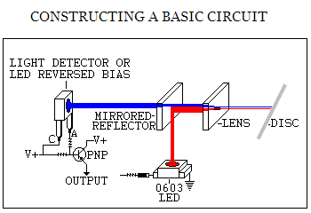
If focused correctly, the beam could burn images, erase re-writable discs and much more if the voltages are correct to work with the organic disc dyes. M-Disc burns would be permanent. In this instance, an LED object can do the job of a laser if the wavelengths match per color.
**After completing a successful burn, we could do a complete surface scan on our optical media to make sure our text and graphics burned to the disc correctly**
In addition to Arduino programming, I'll be creating a C# app to send SCSI commands through USB via a Virtual Serial Com Port in CDC Mode. This will control the Micro-controller which in turn will control the optical drive. This will ease the interfacing as Windows makes it difficult to process IOCTL's, so we'll just communicate with the optical drive directly:

It could also be feasible to implement IMAPI2 functions in this Windows app which handles IO for CD/DVD/BD, though we'd probably need to find a way to implement the SCSI based MMC-5 or MMC-6 command set which enables us to read and write to basically any LBA while they show the expected data layout in their specifications. With the SCSI command set, we can supposedly tell the drive what bitrate to use in kilobytes per second along with a separate speed to use while also being able to select CLV or CAV modes with a constant bitrate.
MMC-5 Multi-Media Commands: http://www.13thmonkey.org/documentation/SCSI/mmc5r04.pdf
SCSI Commands: http://www.seagate.com/staticfiles/support/disc/manuals/scsi/100293068a.pdf
T10 SCSI Hardware Opcodes: SCSI Command Operation Codes (bare metal optical drive command set)
C# IMAPIv2 erase/burn CD/DVD/BD: https://www.codeproject.com/Articles/24544/Burning-and-Erasing-CD-DVD-Blu-ray-Media-with-C-and-IMAPI2
C# IMAPIv2 to burn audio cd: https://www.codeproject.com/Articles/25241/Creating-Audio-CDs-using-IMAPI
According to these specifications, sectors can be marked as either being in the lead-in, program area or lead-out by a single byte. The Lead-in and Lead-out areas are always CAV so we could create a disc image that states all sectors are in the Lead-in area so that all sectors are written in CAV mode by default. Then we can just issue a SCSI command to the drive to hand it a bitrate. The Lead-in and Lead-out areas are concentric circles written in CAV mode while the sectors are 2048 bytes user defined data. We can also declare start and stop LBA's, but the LBA's are seemingly written in CLV spiral VBR mode, so if we want concentric circles with CAV then we state all sectors are in the Lead-in, but request a last possible LBA address for Lead-out from the drive so we can leave room for a lead-out.
Supposedly, we'd write 1's in the Lead-in sectors to leave the disc surface alone and write 0's for the laser to burn some disc dye to create a dull area representing a 0. We'd just need to match up the spindle motor RPM with the correct bitrate so we can write visible images to the disc in the right places. On a test run, we might have slanted or italicized font for being a few microseconds off, but handling things this way, we can verify the data after a burn. On the discs, we declare how large each zone is, how many sectors are in the Lead-in, Lead-out and program area.
Perhaps in the case of drawing images on discs, LBA's are not important. It would be much simpler to state that the entire disc is the Lead-in area.
I'll be updating as things progress with this project 
Please check back often. Thanks!

