


Hi everyone, this is my first time visiting the element 14 community as I am struggling with a project at the moment and I hear that this was a great place to get help with electronics. As I am new, I apologise in advance if this pops up within the wrong community. As the title suggests, my project involves me building a Capacitive Force Sensor, which I have done and have done some initial testing on it using an LCR Bridge and I managed to get the Capacitance to vary when I applied a Force to it.
The main issue i'm having at the moment is with building a circuit in which I can obtain a voltage reading off the sensor which I can then use to find the force by using the equation V=kF^2. So far the circuit designed is as follows:
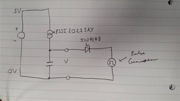
As can be seen from the picture, the circuit consists of a 5V input from a bench power supply and a constant current source, which is represented by a PSSI2021SAY IC (http://assets.nexperia.com/documents/data-sheet/PSSI2021SAY.pdf ) with a 10K ohm resistor connected across pins 4 and 5 to set the current to 0.1mA. The sensor is represented by the Capacitor with the output being measured on an oscilloscope where a Sawtooth wave should be observed. An IN4148 Diode and Pulse Generator are also used.
The pulse generator generates a square wave where the frequency is set by using the following equations:

i/C is inverted to find the frequency. For example, if I were to have a current of 0.1mA and a 1pF capacitor, i/C =1x10^8 V/s which would correspond to 100Mhz which would what the pulse generator would be set to.
For the purposes of testing and calibrating the concept, I have opted for testing fixed capacitors to try and obtain a base reading as my sensors seem to fluctuate a bit.
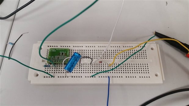
Here is the circuit created up close:
And here is the circuit hooked up to the pulse generator, oscilloscope and bench power supply:
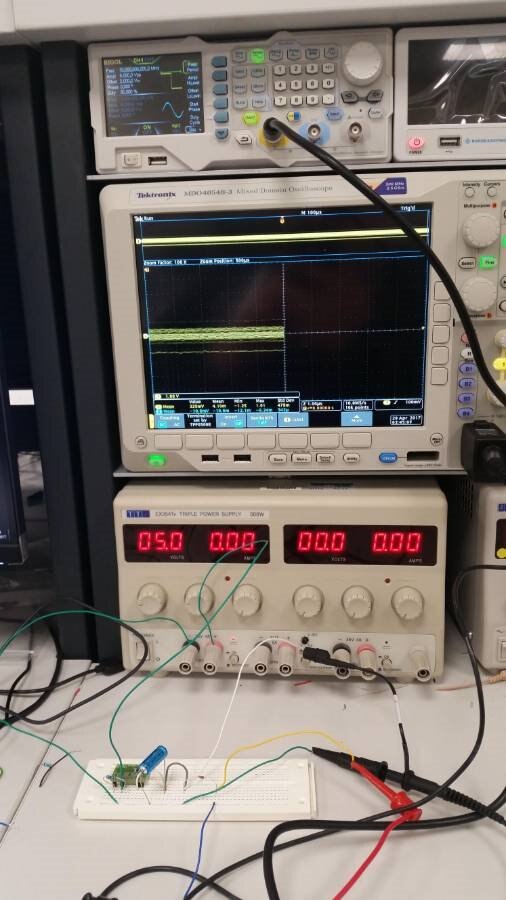
The issue is that I am not getting the desired sawtooth wave output, even if I fiddle around with the frequency. I have used various capacitors to no avail and have checked the circuitry multiple times to try and see if it was built wrong. I have tried grounding the circuit as well using the ground of the power supply and without which doesn't seem to make a difference. The PSSI2021SAY was tested and was found to be working.
Perhaps there is a missing step in my maths? Or the circuit is built wrong? or my power supply and/or pulse generator are configured wrongly? Any help would be greatly appreciated as the project is due to be finished in a few days. Thanks for any help in advance!

