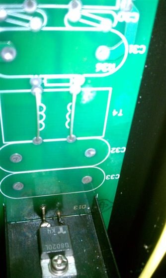
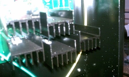
Hello,
one important differentiation we need to make here is whether it is a linear or switch-mode drive. Today, and especially in this power range, pretty much all drive circuits are switch-mode. The motors being used are brushless DC motors in many cases, for which a "frequency inverter" is needed. The minimum number of phases for an electrical motor to effectively determine rotational direction is 3, so you should be seeing three half bridges, or 6 sets of switches in the inverter.
For lower-voltage motors (think forklifts), the currents are very high for the same power, as the voltage is lower. So you'll need more current-handling capability in the switches. Moreover, the worst case condition for the current is determined by the mechanical parts the motor is driving, e.g. when it is blocking, or at startup. Third, the time until any overcurrent protectio ncircuit can react needs to be considered as well. These factors lead us to rather large design margins that need to be implemented, hence the paralleling of so many MOSFETs. In fact, in forklifts it is not uncommon to see 30-40 MOSFETs in parallel.
Key to successful paralleling in linear applications are given in the previous posts. For switching applications, some of this applies as well. The most important factor here is a "good enough" match of the threshold voltage of the MOSFETs. Imagine at turn on: The MOSFET with the lowest threshold voltage will turn on first, and as the gate voltage continues to rise the other MOSFETs will follow. However, that first MOSFET will see high currents, potentially leading to destruction.
On the temperature coefficient, yes MOSFETs have a positive tempco if operated above a certain current level (which is almost always the case in switching power applications). If you look at the diagram of drain current versus gate voltage for different temperatures, you will see all these lines cross in one point, where the temperature coefficient is literally zero.