element14 Community
element14 Community
    Register Log In
  • Site
  • Search
  • Log In Register
  • About Us
  • Community Hub
    Community Hub
    • What's New on element14
    • Feedback and Support
    • Benefits of Membership
    • Personal Blogs
    • Members Area
    • Achievement Levels
  • Learn
    Learn
    • Ask an Expert
    • eBooks
    • element14 presents
    • Learning Center
    • Tech Spotlight
    • STEM Academy
    • Webinars, Training and Events
    • Learning Groups
  • Technologies
    Technologies
    • 3D Printing
    • FPGA
    • Industrial Automation
    • Internet of Things
    • Power & Energy
    • Sensors
    • Technology Groups
  • Challenges & Projects
    Challenges & Projects
    • Design Challenges
    • element14 presents Projects
    • Project14
    • Arduino Projects
    • Raspberry Pi Projects
    • Project Groups
  • Products
    Products
    • Arduino
    • Avnet Boards Community
    • Dev Tools
    • Manufacturers
    • Multicomp Pro
    • Product Groups
    • Raspberry Pi
    • RoadTests & Reviews
  • Store
    Store
    • Visit Your Store
    • Choose another store...
      • Europe
      •  Austria (German)
      •  Belgium (Dutch, French)
      •  Bulgaria (Bulgarian)
      •  Czech Republic (Czech)
      •  Denmark (Danish)
      •  Estonia (Estonian)
      •  Finland (Finnish)
      •  France (French)
      •  Germany (German)
      •  Hungary (Hungarian)
      •  Ireland
      •  Israel
      •  Italy (Italian)
      •  Latvia (Latvian)
      •  
      •  Lithuania (Lithuanian)
      •  Netherlands (Dutch)
      •  Norway (Norwegian)
      •  Poland (Polish)
      •  Portugal (Portuguese)
      •  Romania (Romanian)
      •  Russia (Russian)
      •  Slovakia (Slovak)
      •  Slovenia (Slovenian)
      •  Spain (Spanish)
      •  Sweden (Swedish)
      •  Switzerland(German, French)
      •  Turkey (Turkish)
      •  United Kingdom
      • Asia Pacific
      •  Australia
      •  China
      •  Hong Kong
      •  India
      •  Korea (Korean)
      •  Malaysia
      •  New Zealand
      •  Philippines
      •  Singapore
      •  Taiwan
      •  Thailand (Thai)
      • Americas
      •  Brazil (Portuguese)
      •  Canada
      •  Mexico (Spanish)
      •  United States
      Can't find the country/region you're looking for? Visit our export site or find a local distributor.
  • Translate
  • Profile
  • Settings
Dev Tools
  • Products
  • More
Dev Tools
Forum L298 current sensor pin, convert pulsed current signal to consumption flag
  • Forum
  • Documents
  • Files
  • Members
  • Mentions
  • Sub-Groups
  • Tags
  • More
  • Cancel
  • New
Join Dev Tools to participate - click to join for free!
Actions
  • Share
  • More
  • Cancel
Forum Thread Details
  • State Verified Answer
  • Replies 20 replies
  • Answers 2 answers
  • Subscribers 82 subscribers
  • Views 4244 views
  • Users 0 members are here
Related

L298 current sensor pin, convert pulsed current signal to consumption flag

modelrailwaycat
modelrailwaycat over 10 years ago

Hello,


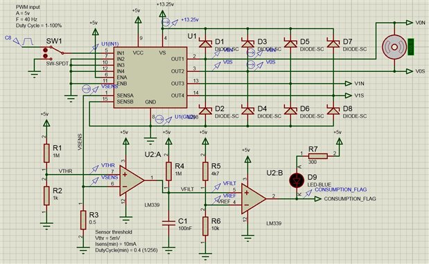
I am designing a small, simple 12V motor controller fed by a L298 H-bridge driver. The H-bridge input pins are supplied by means of PWM at 40 Hz. The motor can be connected or disconnected from the output even with the input and enable on. For this reason, I am interested in adding additional circuitry in order to obtain a binary signal of consumption using the current sensor pins; that is obtain a permanent high level while some current is detected and a permanent low level when no current is detected (after at least 1 period, but this is flexible).


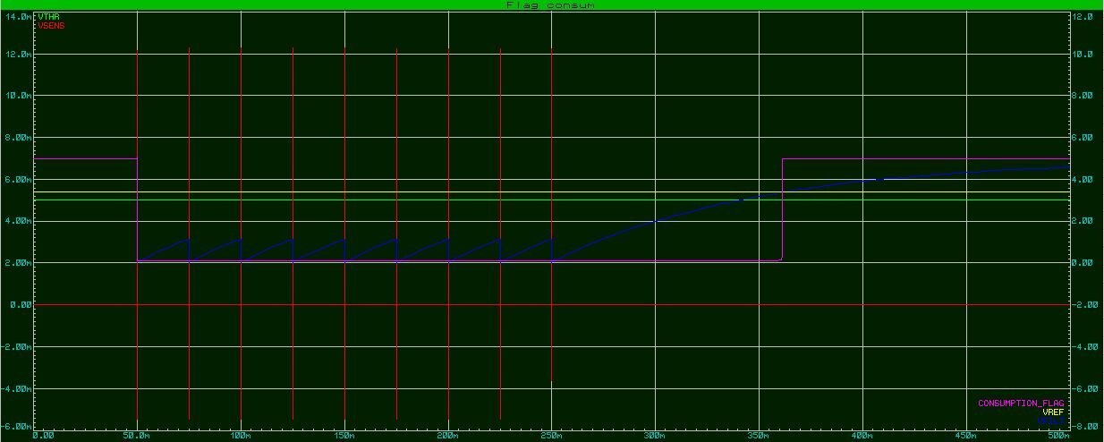
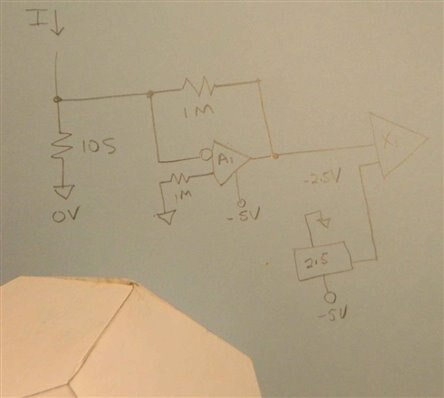
The idea is to use a 0.5 ohm resistor to connect the sense pin to ground, and then use the voltage across the resistor to obtain the signal. I consider that the voltage measured will be from 5 mV to 1V and the Duty Cycle can be down to 1%. Because the sensor signal is also pulsed, I need somehow to filter it and obtain an stable output while consumption is 'on'. The problem is that I had not success to set properly a low-pass filter plus op-amp buffer configuration from this signal working reliably with all the mentioned conditions. I also tried to pre-amplify the sensor signal with another op-amp, then output that into the low-pass filter plus buffer, but had no success too.


Any idea is appreciated. Thank you very much!

  • Sign in to reply
  • Cancel

Top Replies

  • D_Hersey
    D_Hersey over 10 years ago +2 suggested
    Can you draw it up? What op-amp are you using? Not all op amps have common mode input range all of the way to BoS.
  • D_Hersey
    D_Hersey over 10 years ago +2
    "If you are going to reverse the current, you will need to set up a different reference voltage as with everything referred to 0V you will not get a negative swing. And your comparator will have to work…
  • peterjcs23
    peterjcs23 over 10 years ago in reply to modelrailwaycat +1
    Hi John, is your motor turning ok? If you put a DVM across Rsense what voltage do you see when turning and when stationary? Do you have a scope to look at waveforms? Peter
  • modelrailwaycat
    0 modelrailwaycat over 10 years ago

    Hi again,


    Thank you very much to all of you for your support. I think I finally get it work using the concept proposed by Peter, and also changing the filter configuration and inverting the first comparator, so the consumption flag now is 'active low', which is OK. I don't need the reverse operation signal because I have the information from the signals inputed to the LM298.


    Attached is what I tried this time. As you can see, I also changed the voltage threshold to 5mV to avoid problems working near GND in the 1rs comparator. It limits minimum current detection to 10 mA but I think will be OK. With this configuration, the VFILTER voltage is below the reference voltage VREF in the 2nd comparator down to 0,4% PWM Duty Cycle, which is a 1/256 resolution, enough for me, during all the time while PWM action is 'on'. After PWM goes to low, the VFILTER voltage recovers and changes the consumption flag when it goes above 3,4v (VREF). This takes about 110 ms after the last pulse sent, enough for the intended application.


    image

    In the simulation below, the PWM signal starts at 50 ms (the flag goes low) and stops at 250ms. After 110 ms, the flag goes high.

    image

    Do you see any problems with this concept?


    I have to test it in the protoboard to confirm it is OK.


    Thank you very much again!

    • Cancel
    • Vote Up +1 Vote Down
    • Sign in to reply
    • Verify Answer
    • Cancel
  • peterjcs23
    0 peterjcs23 over 10 years ago in reply to modelrailwaycat

    Hi John, glad it's working. By the way what simulator are you using? I like the look of it.


    In the real circuit you may need to add some hysteresis to the LM339s. 1Meg between the + pin and the output pin. Also if the input signals are a bit spiky you can add a 100pF cap between the + pin and -pin. That will kill off any spurious output glitches. You may not see glitches and your filter may kill them anyway, but normally that is what I'd do...Peter

    • Cancel
    • Vote Up +1 Vote Down
    • Sign in to reply
    • Verify Answer
    • Cancel
  • D_Hersey
    0 D_Hersey over 10 years ago

    Not to be an arch-pedant but remember that the LM339 has an OC output.  The output of the left-hand comparator will discharge the capacitor much more swiftly than the pull-up will charge it.  Maybe that is the behavior you desire, IDK.


    As drawn, you are being kinda noodnik regarding PS fluctuation.  You can shunt a cap around the lower legs of your reference strings for a cheap fix.  Or maybe you don't care or maybe the current behavior is what you seek.


    Or use a reference instead of a ladder across the supply.

    • Cancel
    • Vote Up +1 Vote Down
    • Sign in to reply
    • Verify Answer
    • Reject Answer
    • Cancel
  • D_Hersey
    0 D_Hersey over 10 years ago

    The addition of the hysteresis resistor as suggested above is a good way to prevent jitter.  The next step up the path in that regard is to use two comparators, two references and a flip-flop.


    overall - feedback yields stability

    overall + feedback yields oscillation or saturation


    here we want saturation

    • Cancel
    • Vote Up +1 Vote Down
    • Sign in to reply
    • Verify Answer
    • Cancel
  • D_Hersey
    0 D_Hersey over 10 years ago

    If you have a spare -5V supply you could try something along these lines, this might be faster but a little less accurate.  I think Peter had the idea awhile ago, IIRC.


    image

    • Cancel
    • Vote Up +1 Vote Down
    • Sign in to reply
    • Verify Answer
    • Cancel
  • D_Hersey
    0 D_Hersey over 10 years ago

    Here are some chips just made for this:


    Linear Technology - Parametric Search for Reference Plus Comparator or Amplifier

    • Cancel
    • Vote Up +1 Vote Down
    • Sign in to reply
    • Verify Answer
    • Cancel
  • modelrailwaycat
    0 modelrailwaycat over 10 years ago in reply to D_Hersey

    Hi,


    @Peter,

    Software: I use Proteus ISIS. It has enough power for what I need, and also it is interesting the interactive controls (switch, motor, LED,...) during simulation. On the other hand, some components models are missing.

    Hysteresis resistors: if I add a 1M resistor between +pin and output in the 1st comparator, then the voltage threshold (connected to +pin) is bouncing due to the effect of the capacitor, which produces abnormal functionallity of this comparator. How can I avoid that? In the 2nd comparator there is no problem to add it, I think.

    Spiky inputs: I added the caps as suggested.


    @Don,

    OC comparators: yes, precisely this effect has solved the problematic of making the consumption flag remaining active (low) even at low Duty Cycles, thanks to the quick discharge of the capacitor.

    PS fluctuation: if I understood your suggestion right, I can solve this by adding a parallel capacitor to the lower side of the voltage divider, isn't it?

    Hysteresis resistors: yes, we want saturation to provide a 'clean' binary flag. From that I understand that Peter's proposal is the right way, but still I got the problem with the 1st comparator as told above.

    Alternative circuitry: in the application there will not be a -5v supply. By the way, I need 'accuracy' (in terms of stability of the flag during PWM action) rather than speed of the signal, for my particular application.


    Thank you again!

    • Cancel
    • Vote Up 0 Vote Down
    • Sign in to reply
    • Verify Answer
    • Cancel
  • peterjcs23
    0 peterjcs23 over 10 years ago in reply to modelrailwaycat

    ah, I see, there are too many 1M resistors in that chain that includes the reference, the hysteresis and the pull up. Perhaps you could leave out the hysteresis.


    Alternatively, you might improve the circuit with an amplifier on the current sense resistor and you bring the operating current signal up to ~1volt. As Don suggests you could use a Vref for the comparator reference so that you are not dependant on the power rails, which will vary. The comparator reference could be derived with resistors around the 10k level. The 1M pull up could be down to <10k.


    Peter

    • Cancel
    • Vote Up 0 Vote Down
    • Sign in to reply
    • Verify Answer
    • Cancel
  • michaelkellett
    0 michaelkellett over 10 years ago in reply to peterjcs23

    Rather than trying to deal with the tiny current sense signal by amplifiers you could increase the value of the sensor resistor to 10R. It would then drop far too many volts at high currents so you would need to shunt it with a schottky diode capable of handling the full load current.

    The loss in the diode would probably be not much worse than in the 0.5R resistor but you would have  a much bigger sense voltage to work with.


    Of course the linear range of current sensing would be reduced but since you seem only to want on/off detection this shouldn't matter.


    MK

    • Cancel
    • Vote Up 0 Vote Down
    • Sign in to reply
    • Verify Answer
    • Cancel
  • pankaj671
    0 pankaj671 over 7 years ago in reply to modelrailwaycat

    HI john

    i need same ckt for my application .i need to use amplifier + comparator + plus shaping ckt to make sense signal to 5 V TTL compatible to feed it to FPGA.

    Can you help .

    • Cancel
    • Vote Up 0 Vote Down
    • Sign in to reply
    • Verify Answer
    • Cancel
<
element14 Community

element14 is the first online community specifically for engineers. Connect with your peers and get expert answers to your questions.

  • Members
  • Learn
  • Technologies
  • Challenges & Projects
  • Products
  • Store
  • About Us
  • Feedback & Support
  • FAQs
  • Terms of Use
  • Privacy Policy
  • Legal and Copyright Notices
  • Sitemap
  • Cookies

An Avnet Company © 2025 Premier Farnell Limited. All Rights Reserved.

Premier Farnell Ltd, registered in England and Wales (no 00876412), registered office: Farnell House, Forge Lane, Leeds LS12 2NE.

ICP 备案号 10220084.

Follow element14

  • X
  • Facebook
  • linkedin
  • YouTube