


This document shows a brief demonstration on executing wireless uart application using NXP Bluetooth Low Energy Software for the KW40Z wireless microcontroller platforms.
To proceed further the below are the prerequisites:
1. The freedom hardware board i.e FRDM-KW40Z-2 No’s as shipped in a box
2. IAR Tool to compile/build the example of wireless uart project
The Wireless UART application implements both the GATT client and server for the custom Wireless UART profile and service: Wireless UART Service (UUID: 01ff0100-ba5e-f4ee-5ca1-eb1e5e4b1ce0)
Battery Service v1.0 and Device Information Service v1.1
The Wireless UART service is a custom service that implements a custom writable ASCII Char characteristic (UUID: 01ff0101-ba5e-f4ee-5ca1-eb1e5e4b1ce0) that holds the character written by the peer device.
The application behaves at first as a GAP central node. It enters GAP Limited Discovery Procedure and searches for other Wireless UART devices to connect. If the node fails to find any peripherals within seconds, it changes its role to a GAP peripheral. It enters GAP General Discoverable Mode and waits for a GAP central node to connect.
Steps involved:
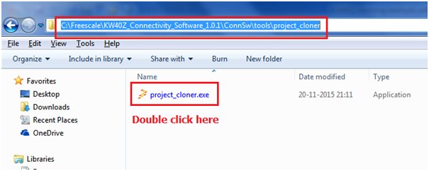
1) Cloning a project: run the Project Cloner application (ConnSw\tools\project_cloner\project_cloner.exe)
2) Building the Binaries using IAR
3) Executing the project using generated binaries
Step -1: Cloning a project
Navigate to the below path
“C:\Freescale\KW40Z_Connectivity_Software_1.0.1\ConnSw\tools\project_cloner”
And run the project cloner application
Now we need to select the path for “codebase path” as shown below

We need to select “C:\Freescale\KW40Z_Connectivity_Software_1.0.1\ConnSw” as its path
Next select the example of wireless uart application to be cloned (Clone example app), and the desired configuration (Clone Configuration).

Under cloned app name provide name of your choice i have given it as “smac_wireless_uart-cloned” and other options as shown below:
And select the destination folder where the project needs to be saved
I am saving this project under a folder “C:\Users\brao\Desktop\cloned conn project”

After cloning you can see the data logging of cloning process

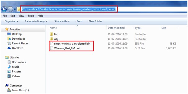
You can see the cloned project in folder
“C:\Users\brao\Desktop\cloned conn project\smac_wireless_uart-cloned”

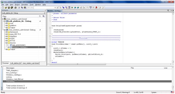
Step-2: Building the Binaries using IAR
Open IAR Tool

Open the cloned IAR workspace “smac_wireless_uart-cloned.eww” from below location
“C:\Users\brao\Desktop\cloned conn project\smac_wireless_uart-cloned”

The KSDK platform libraries are RTOS dependent, so appropriate libraries must be built for the selected RTOS. For any connectivity application, the following Kinetis SDK libraries must be built with the IAR Embedded Workbench for ARM in order to enable the complete board support and RTOS kernel support:
Select the KSDK platform (bare-metal) library project and Build the KSDK platform library project.

It builds with zero error
Next Select the “smac_wireless_uart-cloned” project and build it as did earlier It builds with zero error and an executable *.out is generated
Step-3 Executing the wireless uart using the generated binaries
We need two FRDM-KW40ZFRDM-KW40Z boards to execute this project The binaries are located in the below folder
“C:\Users\brao\Desktop\cloned conn project\smac_wireless_uart-cloned\debug”
We can see inside the “Wireless_UartApp.c” the uart baud rate has been set to 115200
Serial_SetBaudRate (mAppSer, gUARTBaudRate115200_c); //Set 115200 as default baud
You can browse for the other api’s and code flow inside the “Wireless_UartApp.c” file as shown below:
If any changes to be made as per your requirement you have to do it here and rebuild again to get the exe file
Now connect both the boards when connected we can see it in explorer as shown
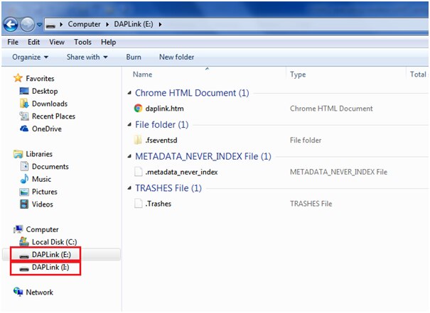
Now copy the generated “smac_wireless_uart-cloned.bin” file from debug folder and paste it into both the DAPLink foders as shown below:

And to the other board's DAPLink

Now open the Putty hyperterminal:
You can see both the boards in device manager listed under ports (COM & LPT)

COM53 board-1 settings:

COM54 board-2 settings:

After flashing the board, the device is in idle mode (all 4 LEDs flashing). To start scanning, press the SW4 button. When in GAP Limited Discovery Procedure of GAP General Discoverable Mode, LED1 is flashing. When the node connects to a peer device, LED1 turns solid. To disconnect the node, hold the SW4 button pressed for 2-3 seconds. The node then re-enters GAP Limited Discovery Procedure.
The application is built to work with a similar application on a different device.
The start screen is blank after the board is reset.
Press the SW4 button on the first board to start scanning for devices. Do the same on the second board. After 5 seconds, the first board enters GAP General Discoverable Mode and the second board connects.
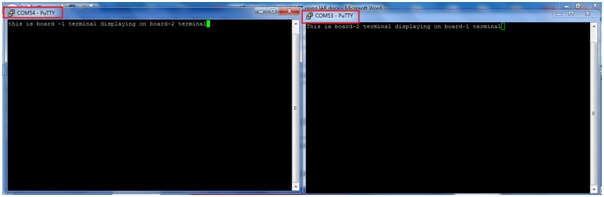
As soon as the LED1 turns solid on both devices, the user can start writing in one of the consoles. The text appears on the other terminal, as shown in the figure below.
Happy Executing the wireless uart application on KW40Z (wireless MCU)... 

