


Here is a tutorial working on to Create an MQX RTOS project with Processor Expert using New Kinetis Design Studio 3.0 IDE and using Kinetis Software development kit (KSDK) 1.2.0. Processor Expert provides a graphical interface for configuring your project and adding useful software components. With the release of the Kinetis SDK, there is a new MQX_KSDK component that is suitable for configuring the version of MQX RTOS that comes with the Kinetis SDK.
Before we begin make sure below requirements are there as setup
Required Hardware and Software:
- Kinetis Design Studio 3.0
(download link: KDS 3.0)
- Kinetis Software Development Kit (KSDK-v1.2.0)
(Download Link Kinetis SDK 1.2 Mainline )
- FRDM-K64F Board configured with JLink Debugger
(The firmware can be downloaded here: Firmware download)
Or loaded with PE micro openSDA driver
- Install ‘KSDK_1.2.0_Eclipse_Update’ you can find the update file and the instructions to install it in
‘C:\Freescale\KSDK_1.2.0\tools\eclipse_update’.
- It is necessary to build KSDK Platform Driver Library (libksdk_platform.a)
Open ‘Getting Started with Kinetis SDK (KSDK) v.1.2.pdf’ located in ‘C:\Freescale\KSDK_1.2.0\doc’ and go to chapter ‘5.3 Build the platform library’.
- Reference of FRDM-K64 user guide for schematic
- Micro USB Cable
Create KDS project using KSDK
Open KDS IDE by double clicking the KDS icon present in your desktop:
It will ask for the Workspace, give the path of your choice and click ‘ok’

Next create a New project by clicking
File -> New -> Kinetis Design Studio Project

Choose project name of your choice, i have given it as “K64+mqx-PE task” and click Next.

You can select device either by ‘Boards’ or ‘Processor’ option
I am selecting the target device by Boards option and selected “FRDM-K64F” and click Next as shown below:

You can see the Device in target board is “MK64FN1M0LL12”
In the next screen you can find below options to be selected in Rapid Application Development window
Select the check box “Kinetis SDK”
And select the radio button “Environment variable” by which default it displays “KSDK_PATH” which is in installed directory.
Make sure that "Processor Expert" is checked as we are creating project using processor expert option.
Next click Finish button and proceed further.

Develop the application
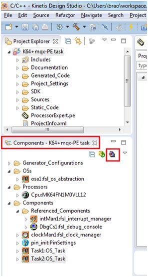
Now you have a new Kinetis SDK project that is ready to be configured with Processor Expert.
Below is the snapshot of the project created in which you can see fsl_os_abstraction under components window.

New Kinetis Design Studio projects enabled with Kinetis SDK and Processor Expert use an Operating System Abstraction (OSA) component which is used to select which RTOS (or no RTOS – baremetal) option you are using. The OSA component will inherit in the selected RTOS component for you. So, don’t add in MQX_KSDK yourself. Let the OSA do it.
In the Components window, under Components, open the OSA component

The Component Inspector window will now show you the Properties and Methods for that component.
From the OS dropdown list, choose MQX_KSDK as your OS

Now you need to set up the MQX_KSDK component for use in your project.
Open the MQX_KSDK component (inherited by the OSA component)

Select the Configuration parameters tab
In the Configuration set, you have the choice of MQX Lite and MQX Standard.
I will chose MQX Lite.
MQX Lite is a light weight configuration of MQX RTOS offering a subset of capabilities. MQX Lite uses static memory allocation by default. If you want to use the RTCS TCP/IP stack, MFS file system, dynamic memory allocation, or some of the advanced features of MQX RTOS, use MQX Standard.

Now select the Shared components tab. You can see that it uses the DbgCs1 component for serial communications.

The same can be seen in components tab under
Components > Referenced_Components > DbgCs1:fsl_debug_console as shown below

Click on the DbgCs1 component under component inspector window you need to select the proper UART port pin settings
You need to tell it which UART should be used for the DbgCs1 component (default serial port).
On the FRDM-K64F, UART 0 connects to the on-board debug circuit for virtual com port to the host PC. Signal names on the schematic, on the debug circuit side, say UART1_RX_TRGMCU and UART1_TX_TRGMCU
Select the UART port as UART0 and Baud rate as 9600 (you can choose your selection)
The settings are selected as shown below:

Creating Tasks:
Here i am creating two tasks Task-1 and Task-2 with different priorities Task-2 being higher priority than Task-1 so that Task-2 is executed first then Task-1 is executed
Now we proceed further by adding Tasks for our project
Processor Expert provides an OS_Task Component that will configure and generate the code framework for tasks.
Click Components Library.

Double click twice on OS_Task to add tasks. It gets added to components of our project as shown below: as we are creating two tasks in our project

The Lowest priority task level is defined under MQX_KSDK components as shown i have given the value of 255

Now click on the Task1 components to configure them.

Set the priority level, for this task the value ranges between 0 to 255 and ‘0’ being highest priority and 255 being the lowest priority
I have selected its value as ‘200’ and its stack size to be 1024 as shown in above picture.
Similarly chose the settings for Task-2 as shown below:

Here the priority selected is 100 as my project requirement is to have higher priority for Task-2 than Task-1(whose priority is 200)
Now i have created project with 2 tasks with different priority
Click the Generate Processor Expert Code button.
You can see configuration files are updated while code generates as shown below:

The task reference code is generated in os_tasks.c as shown below

Just add the printf’s in Task1_task() and Task2_task() as shown below:
printf("This is Task-2 saying Hello \r\n");
printf("This is Task-1 saying World \r\n");
The task function are as shown below:
void Task2_task(os_task_param_t task_init_data)
{
 /* Write your local variable definition here */
 printf(" This is Task-2 saying Hello \r\n");
#ifdef PEX_USE_RTOS
 while (1) {
#endif
 /* Write your code here ... */

 OSA_TimeDelay(10); /* Example code (for task release) */

#ifdef PEX_USE_RTOS
 }
#endif
}
void Task1_task(os_task_param_t task_init_data)
{
 /* Write your local variable definition here */
    printf("This is Task-1 saying World \r\n");

#ifdef PEX_USE_RTOS
 while (1) {
#endif
 /* Write your code here ... */

 OSA_TimeDelay(10); /* Example code (for task release) */


#ifdef PEX_USE_RTOS
 }
#endif
}
Now its time to build our project

You can see the progress of building the project:

The build is completed successfully with no errors:

Let us proceed further for debugging
Debugging and Running the Application
Now we need connect the FRDM-K64 board to our computer via USB cable provided and open the serial hyperterminal window by knowing the port number from Device manager:

In my case it is connected to COM29 port, open any hyperterminal window application ( i am having putty)

My serial port settings are as shown in above picture:
Now click on Debug button from the below window

Below is the execution seen in serial window
You can see that task-2 is executed first by printing
“This is Task-2 saying Hello”
Then the task-1 prints
“This is Task-1 saying World”

I have enclosed the project folder and binaries for quick evaluation.

 | |
|