


Here is a tutorial working on GPIO based interrupt using KSDK. Toggling Led using push button (interrupt based event) on FRDM-K64F board using New Kinetis Design Studio 3.0 IDE and using Kinetis Software development kit (KSDK).
Before we begin make sure below requirements are there as setup
Required Hardware and Software:
- Kinetis Design Studio 3.0
(download link: KDS 3.0)
- Kinetis Software Development Kit (KSDK-v1.2.0)
(Download Link Kinetis SDK 1.2 Mainline )
- FRDM-K64F Board configured with JLink Debugger
(The firmware can be downloaded here: Firmware download)
- Install ‘KSDK_1.2.0_Eclipse_Update’ you can find the update file and the instructions to install it in
‘C:\Freescale\KSDK_1.2.0\tools\eclipse_update’.
- It is necessary to build KSDK Platform Driver Library (libksdk_platform.a)
Open ‘Getting Started with Kinetis SDK (KSDK) v.1.2.pdf’ located in ‘C:\Freescale\KSDK_1.2.0\doc’ and go to chapter ‘5.3 Build the platform library’.
- Reference of FRDM-K64 user guide for schematic
- Micro USB Cable
Create KDS project using KSDK
Open KDS IDE by double clicking the KDS icon present in your desktop:
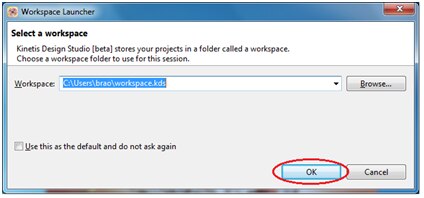
It will ask for the Workspace, give the path of your choice and click ‘ok’
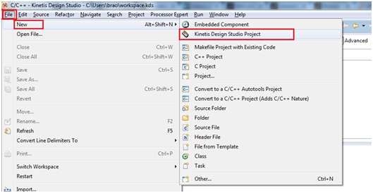
Next create a New project by clicking
File -> New -> Kinetis Design Studio Project
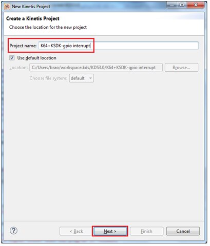
Choose project name of your choice, i have given it as “K64+KSDK-gpio interrupt” and click Next.
You can select device either by ‘Boards’ or ‘Processor’ option
I am selecting the target device by Boards option and selected “FRDM-K64F” and click Next as shown below:
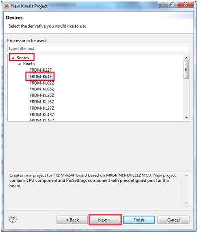
You can see the Device in target board is “MK64FN1M0LL12”
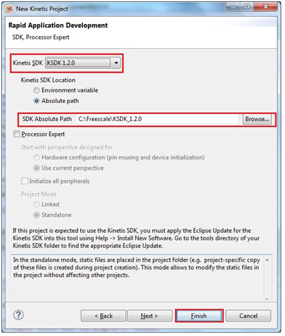
In the next screen you can find below options to be selected in Rapid Application Development window
Select the check box “Kinetis SDK”
And select the radio button “Environment variable” by which default it displays “KSDK_PATH” which is in installed directory.
Make sure that "Processor Expert" is not checked.
Next click Finish button and proceed further.
Develop the application
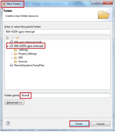
Right click over project folder and select New > Folder to create a new folder inside ‘project’ folder.
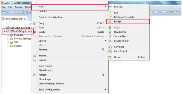
Name this folder ‘Board’ and click ‘Finish’.
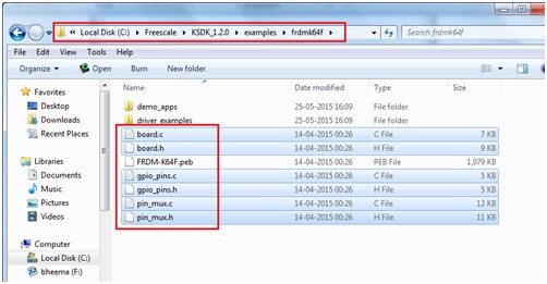
Go to <C:\Freescale\KSDK_1.2.0\examples\frdmk64f> and copy all the source files (except the file FRDM-K64F.peb) in this folder to the folder ‘Board’ that was created in the project.
- board.c
- board.h
- gpio_pins.c
- gpio_pins.h
- pin_mux.c
- pin_mux.h
Right click copy the files and go to KDS project explorer select folder ‘Board’ right click and paste it.

It looks like as shown below in KDS window
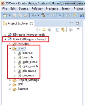
board.c/h: The header file contains board board-specific configuration macros for things such as debug terminal configuration, push buttons, LEDs and other board board-specific items. The C file contains clock and oscillator initialization functions.
gpio_pins.c/h: Definitions used by the KSDK GPIO driver for the platform’s GPIO pins. These include push buttons and LEDs, but can include other items such as interrupt pins for external sensors, for example.
pin_mux.c/h: Contains peripheral-specific pin mux configurations. These functions can be called by the hardware_init() function or individually by the demo application.
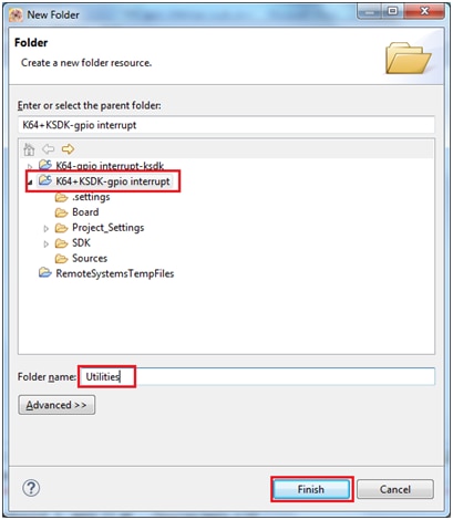
Now create another folder “Utilities” inside our project folder as we did earlier.
Copy the below 2 files to this folder as we did earlier:
fsl_debug_console.c and fsl_debug_console.h
you can find them from below folders:
C:\Freescale\KSDK_1.2.0\platform\utilities\src\fsl_debug_console.c
C:\Freescale\KSDK_1.2.0\platform\utilities\inc\fsl_debug_console.h
fsl_debug_console.c/h: Provides initialization and basic functionality for the UART module that is connected to the debug interface.
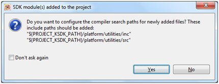
NOTE: After copying ‘fsl_debug_console.c’ to utilities folder the prompt below may appear, in this case click ‘Yes’ and continue.
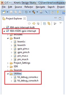
After copying these 2 files into folder ‘Utilities’ it looks as shown below:
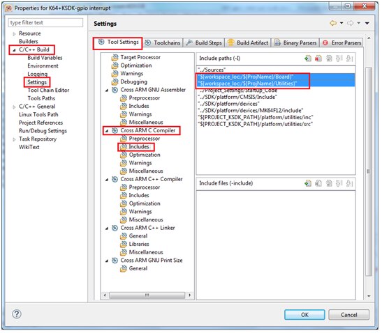
Now we need to add these newly added folders to our ‘include paths’ into our project.
Select project folder, right click and select properties as shown below:

Then goto
“Project > Properties > C/C++ Build > Settings > Cross ARM C compiler > includes”
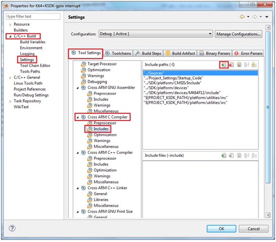
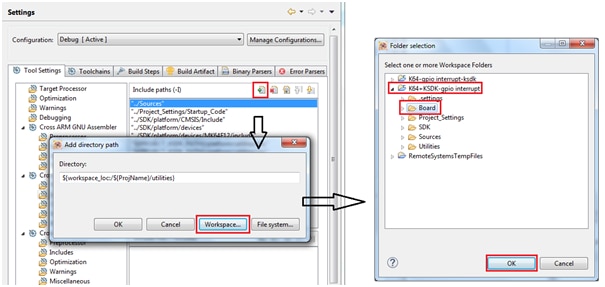
And add the Board and Utilities folder paths into this section as shown in below snapshots
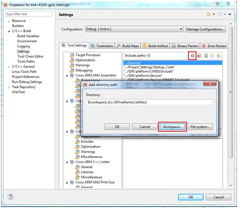
Select Workspace > project folder and “Board” folder as shown below
Next, do similar way and add “Utilities” folder into include path:
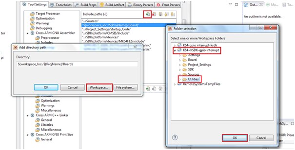
After adding the paths it looks as shown below
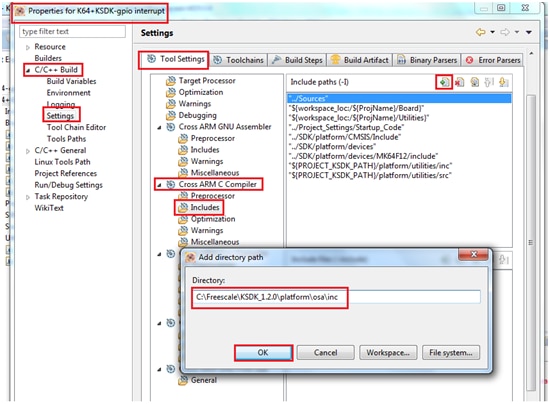
Now you need to add platform related include paths that are required for build the project:
You need to add the below 4 paths to
Properties > C/C++ Build > Settings > Cross ARM C compiler > includes
C:\Freescale\KSDK_1.2.0\platform\osa\inc
C:\Freescale\KSDK_1.2.0\platform\hal\inc
C:\Freescale\KSDK_1.2.0\platform\system\inc
C:\Freescale\KSDK_1.2.0\platform\drivers\inc
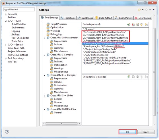
After adding all the 4 paths it looks as shown below:
Build the platform driver library
Before building and debugging any demo application in KSDK, the driver library project should be built to generate the library archives: ksdk_platform_lib.a. Because this library contains all binary codes for HAL and the peripheral drivers specific to the chip, each SoC has its own platform.a library archives.
We need to Importing platform library from the KSDK installation path and build the library, follow below steps to import and build the platform library.
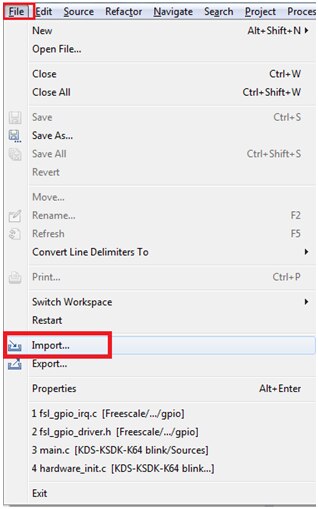
Open the KDS IDE by giving your default workspace and select ‘import’ option as shown below:
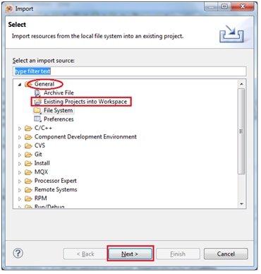
Select File>Import
Next select the option “Existing projects into Workspace” from General Tab and click “Next”
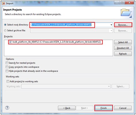
Select the below path
“C:\Freescale\KSDK_1.2.0\lib\ksdk_platform_lib\kds\K64F12”
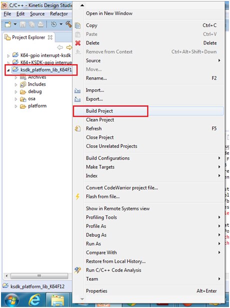
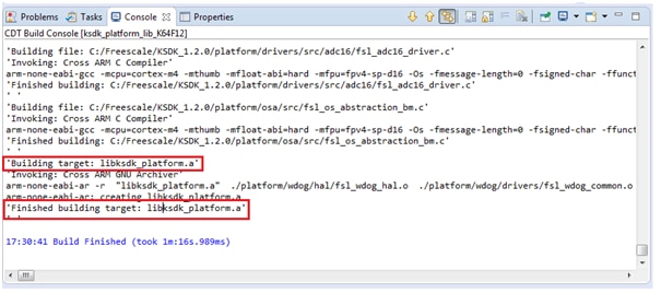
Now build this project as shown below:
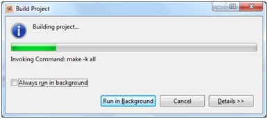
After successfully build you can see the library “libksdk_platform.a” is created under folder:
“C:\Freescale\KSDK_1.2.0\lib\ksdk_platform_lib\kds\K64F12\debug”
Adding the Platform Library to our project
We need to provide this path in our Newly created project.
Goto Project > Properties > C/C++ Build > Settings > Cross ARM C++ Linker > Miscellaneous
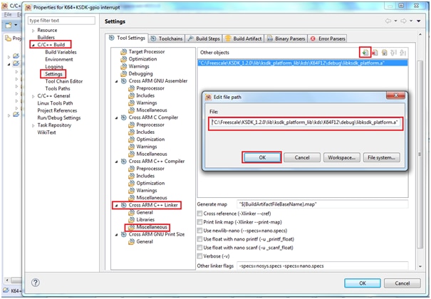
Click on “Apply” and then click “ok”
Now we have added all required include paths and libraries for our project we can precede further in writing our code:
Open the main.c file from source folder:
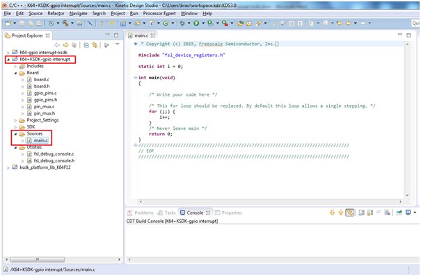
Delete all the contents and paste the below code:
#include"fsl_device_registers.h"
#include "board.h"
#include "pin_mux.h"
#include "fsl_clock_manager.h"
#include "fsl_debug_console.h"
#include <stdio.h>
int main(void)
{
/* enable clock for PORTs */
CLOCK_SYS_EnablePortClock(PORTA_IDX);
CLOCK_SYS_EnablePortClock(PORTB_IDX);
CLOCK_SYS_EnablePortClock(PORTC_IDX);
CLOCK_SYS_EnablePortClock(PORTE_IDX);
/* Init board clock */
BOARD_ClockInit();
dbg_uart_init();
printf("\nHello World! \r\n");
printf("\nPress SW2 to Toggle LED. \r\n");
// initialize the GPIO interrupt for push button for falling edge
switchPins[0].config.interrupt = kPortIntFallingEdge;
// Initializes GPIO driver
GPIO_DRV_Init(switchPins, ledPins);
while(1)
{
}
return 0;
} //end of main
// Define PORTC_IRQHandler (sw1) if GPIO_INTERRUPT is set
void PORTC_IRQHandler()
{
GPIO_DRV_ClearPinIntFlag (kGpioSW2); // Clear IRQ flag
GPIO_DRV_TogglePinOutput(BOARD_GPIO_LED_BLUE); // Toggle blue LED
printf("\n Switch is pressed \r\n");
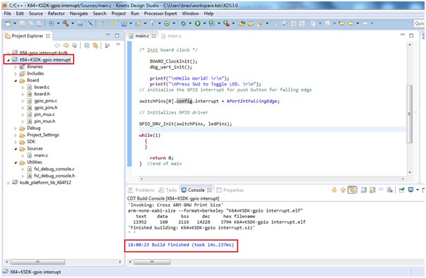
}Now it’s time to clean and compile/Build the project
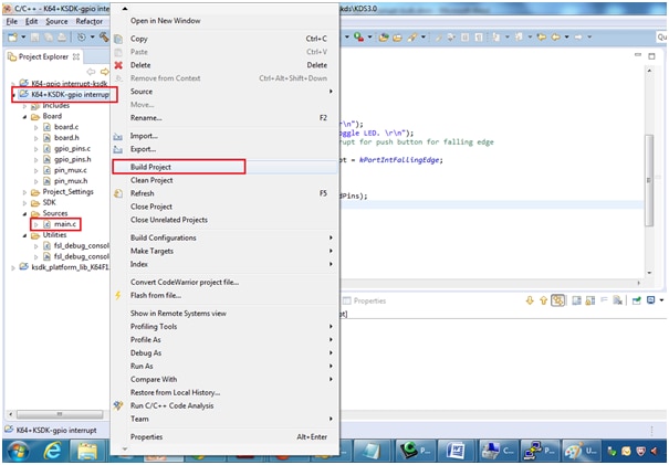
Or click on hammer button as shown

You can see the build result
Debug the application
Now we will proceed further for debugging and test our written code:
Go to menu Run > Debug Configurations
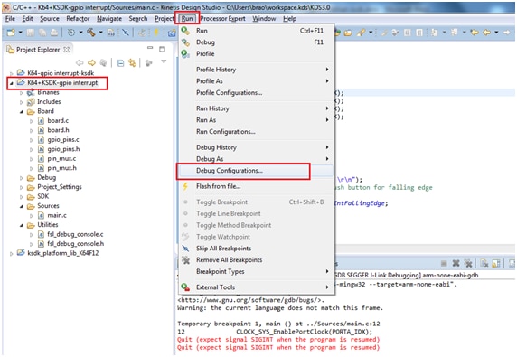
Select GDB Segger J-Link Debugging option as shown below:
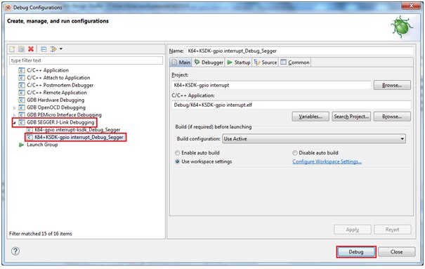
Click on Debug and proceed
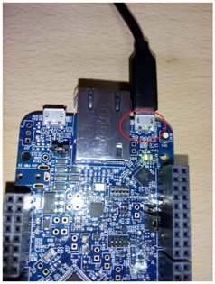
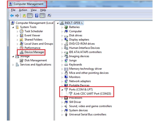
Now we need connect the FRDM-K64 board to our computer via USB cable provided and open the serial hyperterminal window by knowing the port number from Device manager:
In my case it is connected to COM23 port, open any hyperterminal window application ( i am having putty)
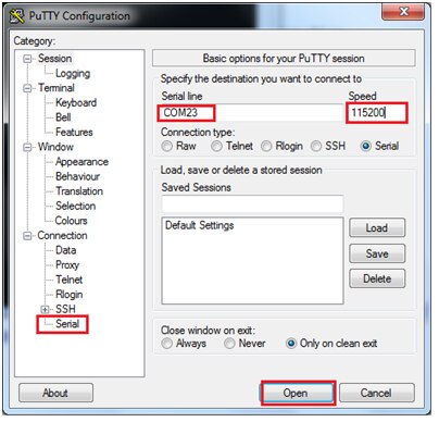
My serial port settings are as shown in above picture:
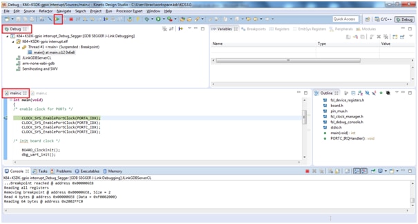
Now click on Debug button from the below window
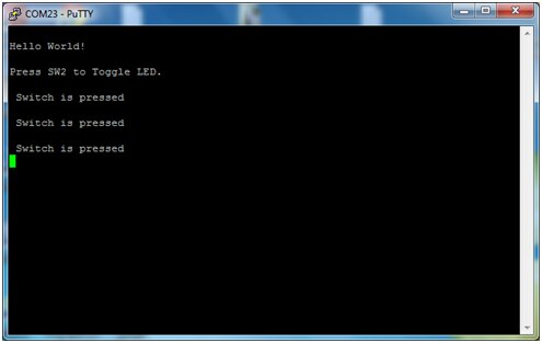
Below is the execution seen in serial window
I have enclosed the project folder and binaries for quick evaluation
You can watch the output recording for this project:
Happy Toggling using interrupt using KDS3.0 + KSDK 1.2.0

 | |
