


Here is a project created to interface and explore the features of FXOS8700 sensor available onboard with K64F freedom board.
FXOS8700CQ is a small, low-power, 3-axis linear accelerometer and 3-axis magnetometer combined into a single package. The device features a selectable I2C or point-to-point SPI serial interface with 14-bit accelerometer and 16-bit magnetometer ADC resolution along with smart-embedded functions.
Before we start this project below are the pre-requisites:
- KDS software tool from Freescale
- FRDM-K64F Freedom development board
Let’s start on creating a project to interface this sensor board using Kinetis Design studio on Processor Expert platform.

Next select the device: you have 2 options for selecting it, one is by “Boards” and other is by “Processors” i am selecting it from the “Boards” option.

Select the board part number FRDM-K64 and proceed further
Make the selection of processor expert in standalone as shown below:

Click finish
You can see the project creation progress bar

Now select the pin settings from components view and select the I2C section as shown below:

As the sensor FXOS8700 are physically connected to I2C pins of K64 board toPTE24 and PTE25.
Expand the I2C window and assign I2C0 (channel-0) SCL-> PTE24 and I2C0 (channel-0) SDA -> PTE25 as shown in below snap shot

Next select UART window from pin configuration main menu as shown below:
As UART0’s RX is connected to PTB16 and UART’s TX is connected to PTB17.
This UART port pins are required for console terminal output.

Next we need to add FXOS8700 device module which is available in component library.

Double click on the FXOS8700CQ module so that it is added to our project.
Automatically its referenced components get added to the components of project.
Click on WAIT1 and ok button for adding it to reference component.

WAIT1 and GI2C1 modules gets added as shown below.

Click on FXOS8700CQ component and configure the settings as shown below:
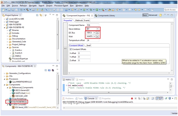
Make sure slave address is “1D” and there are 2 dependant components GI2C1 and WAIT1 for FXOS component module
Next double click on GI2C1: GenericI2C module to set the parameters.
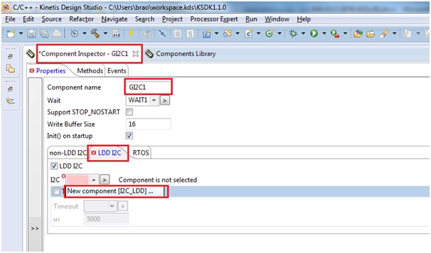
Next click on “>” button

You need to assign the I2C channels, and I2C pins for this module
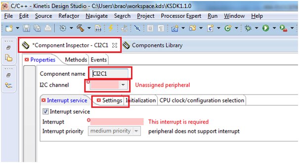
As this board is connected to sensor through I2C channel 0 and we had assigned the same earlier in pins configuration i.e I2C0 (channel-0) SCL-> PTE24 and SDA -> PTE25
Now set the parameters of the I2C module as shown below:

Next add the ConsoleIO component module from component library as shown below:

Double click on the module component to add to our project:

Next click on ConsoleIO_Serial_LDD button as shown below:

We have configured UART0 as shown below:

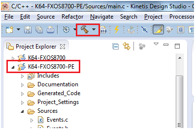
Now generate the project by clicking the below shown button

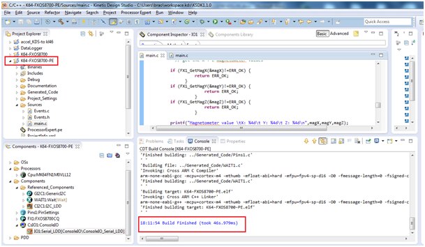
It Builds with no errors as shown below:

Now we are going to add our code in “main.c” file
#include "Cpu.h"
#include "Events.h"
#include "Pins1.h"
#include "FX1.h"
#include "GI2C1.h"
#include "WAIT1.h"
#include "CI2C1.h"
#include "CsIO1.h"
#include "IO1.h"
/* Including shared modules, which are used for whole project */
#include "PE_Types.h"
#include "PE_Error.h"
#include "PE_Const.h"
#include "IO_Map.h"
#include "PDD_Includes.h"
#include "Init_Config.h"
/* User includes (#include below this line is not maintained by Processor Expert) */
/*lint -save -e970 Disable MISRA rule (6.3) checking. */
int main(void)
/*lint -restore Enable MISRA rule (6.3) checking. */
{
/* Write your local variable definition here */
/*** Processor Expert internal initialization. DON'T REMOVE THIS CODE!!! ***/
PE_low_level_init();
/*** End of Processor Expert internal initialization. ***/
/* Write your code here */
int16_t x,y,z,xm,ym,zm;
int16_t value1, value2, value3, addr;
uint8_t ret;
byte res = ERR_OK;
int16_t *data[3];
uint8_t who, temp;
uint16_t magX, magY, magZ;
printf("Hello\n");
FX1_Init();
for(;;) {
/* get WHO AM I values */
if (FX1_WhoAmI(&who)!=ERR_OK) {
return ERR_FAILED;
}
printf("Who Am I value in decimal \t: %4d\n",who);
for(xm=0;xm<=30000;xm++); //delay
/* get raw temperature values */
if (FX1_GetTemperature(&temp)!=ERR_OK) {
return ERR_FAILED;
}
printf("RAW Temperature value in decimal \t: %4d\n",temp);
for(xm=0;xm<=30000;xm++); //delay
//set up registers for accelerometer and magnetometer values
if (FX1_WriteReg8(FX1_CTRL_REG_1, 0x00) != ERR_OK) {
return ERR_FAILED;
}
if (FX1_WriteReg8(FX1_M_CTRL_REG_1, 0x1F) != ERR_OK) {
return ERR_FAILED;
}
if (FX1_WriteReg8(FX1_M_CTRL_REG_2, 0x20) != ERR_OK) {
return ERR_FAILED;
}
if (FX1_WriteReg8(FX1_XYZ_DATA_CFG, 0x00) != ERR_OK) {
return ERR_FAILED;
}
if (FX1_WriteReg8(FX1_CTRL_REG_1, 0x0D) != ERR_OK) {
return ERR_FAILED;
}
// get the X Y Z accelerometer values
x = FX1_GetX();
y = FX1_GetY();
z = FX1_GetZ();
printf("Accelerometer value \tX: %4d\t Y: %4d\t Z: %4d\n",x,y,z);
for(xm=0;xm<=30000;xm++); //delay
// get the X Y Z magnetometer values
if (FX1_GetMagX(&magX)!=ERR_OK) {
return ERR_OK;
}
if (FX1_GetMagY(&magY)!=ERR_OK) {
return ERR_OK;
}
if (FX1_GetMagZ(&magZ)!=ERR_OK) {
return ERR_OK;
}
printf("Magnetometer value \tX: %4d\t Y: %4d\t Z: %4d\n",magX,magY,magZ);
for(xm=0;xm<=30000;xm++); //delay
}
/* For example: for(;;) { } */
/*** Don't write any code pass this line, or it will be deleted during code generation. ***/
/*** RTOS startup code. Macro PEX_RTOS_START is defined by the RTOS component. DON'T MODIFY THIS CODE!!! ***/
#ifdef PEX_RTOS_START
PEX_RTOS_START(); /* Startup of the selected RTOS. Macro is defined by the RTOS component. */
#endif
/*** End of RTOS startup code. ***/
/*** Processor Expert end of main routine. DON'T MODIFY THIS CODE!!! ***/
for(;;){}
/*** Processor Expert end of main routine. DON'T WRITE CODE BELOW!!! ***/
} /*** End of main routine. DO NOT MODIFY THIS TEXT!!! ***/
/* END main */
/*!
** @}
*/
/*
** ###################################################################
Explanation of code:
if (FX1_WhoAmI(&who)!=ERR_OK) {
return ERR_FAILED;
}
The FX1_WhoAmI( ) function Returns the value of the WHO_AM_I (0x0D) register. The return value is stored in variable ‘who’ its value is “199” in decimal and ‘C7’ in Hex which is printed in output terminal
if (FX1_GetTemperature(&temp)!=ERR_OK) {
return ERR_FAILED;
}
The function ‘FX1_GetTemperature( )’ reads the value from the register 0x51 which returns the temperature of the die as signed 8bit and stores in variable temp, this value
Below are the setup values written to the registers to get the magnetometer and accelerometer values
if (FX1_WriteReg8(FX1_CTRL_REG_1, 0x00) != ERR_OK) {
return ERR_FAILED;
}
write 0000 0000 = 0x00 to accelerometer control register 1 to place FXOS8700 into standby
[7-1] = 0000 000
[0]= active=0
if (FX1_WriteReg8(FX1_M_CTRL_REG_1, 0x1F) != ERR_OK) {
return ERR_FAILED;
}
write 0001 1111 = 0x1F to magnetometer control register 1
[7]: m_acal=0: auto calibration disabled
[6]: m_rst=0: no one-shot magnetic reset
[5]: m_ost=0: no one-shot magnetic measurement
[4-2]: m_os=111=7: 8x oversampling (for 200Hz) to reduce magnetometer noise
[1-0]: m_hms=11=3: select hybrid mode with accel and magnetometer active
if (FX1_WriteReg8(FX1_M_CTRL_REG_2, 0x20) != ERR_OK) {
return ERR_FAILED;
}
write 0010 0000 = 0x20 to magnetometer control register 2
[7]: reserved
[6]: reserved
[5]: hyb_autoinc_mode=1 to map the magnetometer registers to follow the accelerometer registers
[4]: m_maxmin_dis=0 to retain default min/max latching even though not used
[3]: m_maxmin_dis_ths=0
[2]: m_maxmin_rst=0
[1-0]: m_rst_cnt=00 to enable magnetic reset each cycle
if (FX1_WriteReg8(FX1_XYZ_DATA_CFG, 0x00) != ERR_OK) {
return ERR_FAILED;
}
write 0000 0001= 0x00 to XYZ_DATA_CFG register
[7]: reserved
[6]: reserved
[5]: reserved
[4]: hpf_out=0
[3]: reserved
[2]: reserved
[1-0]: fs=00 for accelerometer range of +/-2g range with 0.244mg/LSB
if (FX1_WriteReg8(FX1_CTRL_REG_1, 0x0D) != ERR_OK) {
return ERR_FAILED;
}
write 0000 1101b = 0x0D to accelerometer control register 1
[7-6]: aslp_rate=00
[5-3]: dr=001=1 for 200Hz data rate (when in hybrid mode)
[2]: lnoise=1 for low noise mode
[1]: f_read=0 for normal 16 bit reads
[0]: active=1 to take the part out of standby and enable sampling
Now it’s time to build the project:

You can see the build is finished successfully with no errors
Now it is ready to debug/execute
Click on Debug configuration as shown below:


Then it shows the project name automatically as “K64-FXOS8700-PE_Debug_Segger”
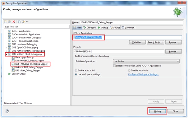
Now connect the K64 board to OPEN SDA port to your computer through USB cable, Then click on Debug button.
You can see below Debug window screen

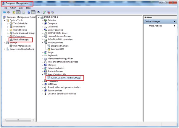
Make sure you have open the corresponding hyperterminal window from your ‘Computer Management’ Device manager window:
In my case it is connected to COM23 port
Now click on green ‘Resume’ button

Open COM23 port from any of the hyper terminal application (putty in my case)
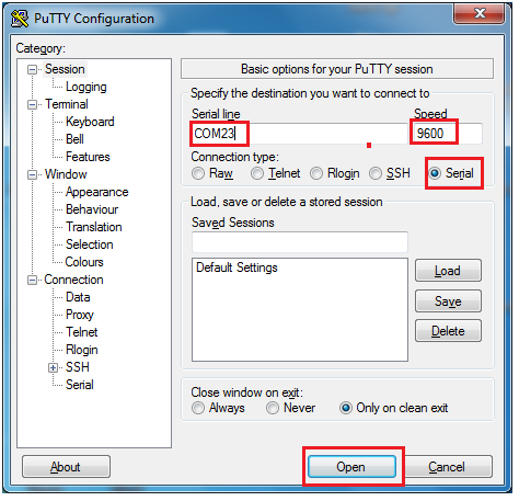
You can see the output of the accelerometer/magnetometer values in hyper terminal as shown below:

Happy Sensing 
Top Comments