


Here is a tutorial for toggling 3-led’s by pressing one switch using interrupt logic implemented using FRDM-K64F on Kinetis Design Studio.
Before i start my project make sure to have below requisites:
- KDS software installed in your PC You can download from Here
- FRDM-K64FFRDM-K64F board
- load Debug driver to K64F board and configuring it in KDS tool (refer to my earlier blog Here)
- Reference of FRDM-K64 user guide for schematic (download from Here)
So lets start in creating a new project using KDS IDE
Open KDS IDE by double clicking the KDS icon present in your desktop:
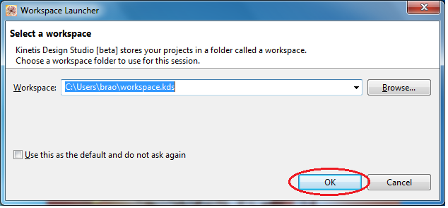
It will ask for the Workspace, give the path of your choice and click ‘ok’
After opening you can see the KDS welcome window as shown here

Create a New project as shown below:
File -> New -> Kinetis Design Studio Project

Choose project name of your choice, i have given it as “RGB_Switch Interrupt-K64”

Select Device “MK64FN1M0XXX12” from the filter as shown
Kinetis K -> MK60->MK64F(120MHz) -> MK64FN1M0XXX12

Now select the option “Use Processor Expert for configuration” and uncheck “Use Kinetis SDK for headers, drivers” and click finish.

You can see the progress bar creating all required header files and libraries..Etc

After completion you can see below project window

Click on CPU, you can see the clock settings, i am using the default settings as shown below i.e the clock source is from internal oscillator with reference clock of 32.768 KHz and Fast internal reference clock is 4 MHz.

Now as per the requirement i am toggling the three LED’s i.e Red, Blue, Green using button press as an interrupt driven GPIO.
So i need to add 3- logic device driver components for LED as shown:

Now right click on Bit0_LDD and add to project 3 times as we need three LED components:

Rename the components as LED_R, LED_G, LED_B as shown

Refer to below schematic of K64 board the 3 LED’s are connected to Port-B and Port-E pins

| LED | K64 |
|---|---|
| RED | PTB22/SPI2_SOUT/FB_AD29/CMP2_OUT |
| BLUE | PTB21/SPI2_SCK/FB_AD30/CMP1_OUT |
| GREEN | PTE26/ENET_1588_CLKIN/UART4_CTS_b/RTC_CLKOUT/USB0_CLKIN |
You can see these LED’s are connected in active-Low connection, i.e common Anode, we should provide Low signal to port pins to glow a LED.
Configure the below settings for 3 LED’s, Double click on the LED_R and provide the below setting
RED LED settings: connected to PTB22 port pin with initial value to be ‘1’ (i.e LED is in off condition)

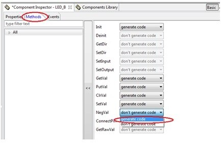
Make sure under ‘Methods’ tab you select “Generate code” for ‘NegVal’ as shown below

Green LED’s setting: connected to PTE26 port pin with initial value to be ‘1’ (i.e LED is in off condition)

Select Generate code for NegVal as shown below:

Blue LED setting: connected to PTB21 port pin with initial value to be ‘1’ (i.e LED is in off condition)

“generate code” for NegVal as shown below:
Next we need to add component for switch acting as interrupt: external interrupt logic device driver (ExtInt_LDD) as shown below:

Select ExtInt_LDD and Double click or right click and add to project.
Configure the settings for this interrupt driver as shown below: as K64F board has the switch (SW2) which is connected to PTC6 port pin, we have assigned this port pin to the external interrupt source with rising edge.

The switch is connected to PTC6 and we have configured it as interrupt driven signal
Now we need to generate code as shown below:

Now all required driver files for LED and ExtInt are generated as shown below:

Now we need to write our code:
Our requirement here is to toggle all the three RGB LED’s one-by-one based on interrupt driven switch press
SW press Red ‘on’ and Green, Blue ‘off’
Next time SW press Green ‘on’ and Red, Blue ‘off’
Next time SW press Blue ‘on’ and Red, Green ‘off’
And carry on the sequence.
‘Events.c’ file in our project has the Interrupt service routine function:
ExtInt_LDD will generate a function as shown:
void EInt1_OnInterrupt(LDD_TUserData *UserDataPtr)
{
/* Write your code here ... */
}
We need to handle ISR
We will assign one global variable ‘x’ in the ‘Events.c’ file and increment this every time when SW is pressed i.e interrupt occurs.
int x=0; // global variable assigned for interrupt
void EInt1_OnInterrupt(LDD_TUserData *UserDataPtr)
{
/* Write your code here ... */
x++; // increment the value when SW is pressed interrupt occurs
}
Now we need to write our code in ‘main.c’ file
extern int x; // we are using the variable declared in ‘Events.c’
Below are lines of codes written
int y;
LDD_TDeviceData *Red_Ptr, *Green_Ptr, *Blue_Ptr; // declaring pointer variable for Red, Blue, Green LED’s
for(;;) {
y=x % 3; // in order to detect the key press we are using modulo operator
if(y==1){
LED_G_SetVal(Green_Ptr); // switch off Green LED
LED_B_SetVal(Blue_Ptr); // switch off Blue LED
LED_R_NegVal(Red_Ptr); // Toggle RED LED
}
if (y==2)
{
LED_R_SetVal(Red_Ptr); // switch off Red LED
LED_B_SetVal(Blue_Ptr); // switch off Blue LED
LED_G_NegVal(Green_Ptr); // Toggle Green LED
}
if (y==0)
{
LED_R_SetVal(Red_Ptr); // switch off RED LED
LED_G_SetVal(Green_Ptr); // switch off Green LED
LED_B_NegVal(Blue_Ptr); // Toggle Blue LED
}
}
Code explanation:
Whenever key press is detected a global variable(x) is incremented inside ISR.
We do modulo operation for this incremented value(x) based on the modulo operation output we can decide on the key press occurrence, this is explained below:
x | y=x%3 | Y | Red Led | Green Led | Blue Led |
0 | 0 % 3 | 0 | off | off | Toggle |
1 | 1 % 3 | 1 | Toggle | off | off |
2 | 2 % 3 | 2 | off | Toggle | off |
3 | 3 % 3 | 0 | off | off | on |
4 | 4 % 3 | 1 | Toggle | off | off |
5 | 5 % 3 | 2 | off | Toggle | off |
6 | 6 % 3 | 0 | off | off | on |
7 | 7 % 3 | 1 | Toggle | off | off |
8 | 8 % 3 | 2 | off | Toggle | off |
You can clean the project once and Build the project to check that your project configuration is done properly and build successfully.

Build progress as shown:

Build success as shown below:

Now we need to setup for Debug configuration:
As a pre-requisite the board is loaded with “JLink_OpenSDA_V2.bin” OpenSDA_V2 application driver file. And same will be used for connecting hardware to PC.

Select ‘GDB SEGGER J-Link Debugging' and double click or right click and select ‘New’

You can see a default name as project name as shown below: make sure under ‘Main’ tab C/C++ application there is *.elf file name of your project.

Next click on Debuger tab check ‘Device name’ field by default it is blank.

Now specify device name “MK64FN1M0xxx12” and click on apply and close the Debug configuration window as shown below:

Now connect FRDM-K64F board to PC through USB mini connector connecting to “SDA USB” port of board as shown:

Click on Debug icon as shown and select Debug Configuration and proceed to debug your project:

Click on Debug

proceed further y clicking 'accept' for J-Link connection Terms of use.

Now you can see the Debug window opens ready for single stepping or Running the project as shown:

Click on Resume button or press ‘F8’ button for executing the project.
You can see the output as shown

Attached is the video recording of the project execution and also the project folder for quick reference.
