


Here is a project created to interface SHT11 click module (humidity and temperature sensor) with FRDM-KL05Z freedom board.
Before we start this project below are the pre-requisites:
- KDS software tool from Freescale
- FRDM-KL05Z Freedom development board
- FRDM-K64F click shield / Arduino UNO click shield [MIKROE-1581] (optional)
- SHT1x click module [MIKROE-949]
SHT11 details:
http://www.mikroe.com/click/sht1x/
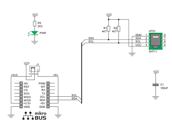
SHT11 Click is an accessory board in mikroBus form factor. It includes a digital humidity and temperature sensor SHT11. A unique capacitive sensor element is used to measure relative humidity while the temperature is measured by a band-gap sensor. Serial I2C interface and factory calibration, allow easy and fast system integration. Board is set to use 3.3V power supply by default.

Communication with the SHT11 sensor is done using I2C interface. Temperature can be represented in 12-bit or 14-bit format in operating range from -40 to +100°C with accuracy of +/- 0.5°C at room temperature. Humidity can be represented in 8-bit or 12-bit resolution with +/- 3% accuracy.
The schematic of the click board is as shown below:
So let me start from creating the new project:
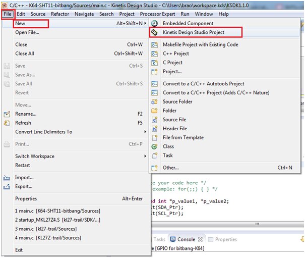
Create a New KDS project name as shown, i have selected “KL05_SHT11x”

Next select the device: you have 2 options for selecting it, one is by “Boards” and other is by “Processors” i am selecting it from the “Processors” option as shown below:
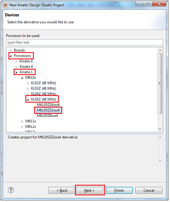
Select processor part number present on the board FRDM-KL05Z (“MKL05Z32VLF4” ) and proceed further.
Make the selection of processor expert in standalone as shown below:
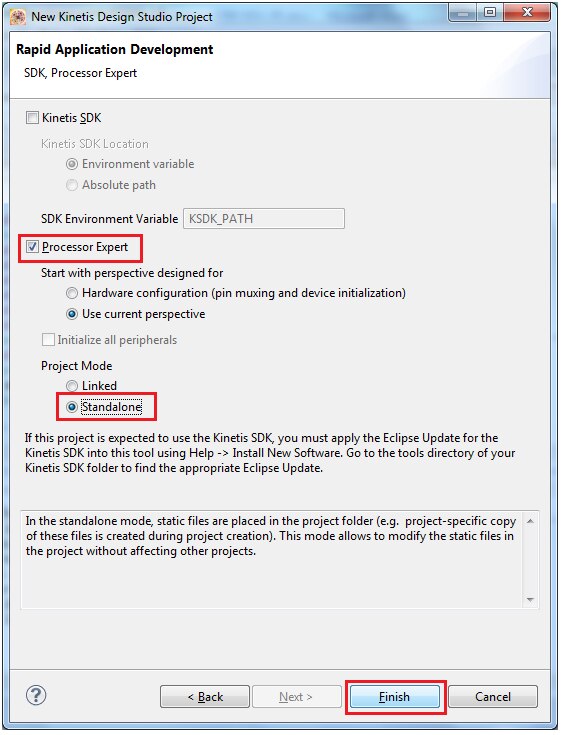
Click finish to proceed further.
Now we will proceed further by adding our components: as we are implementing the I2C logic using Bit Banging we need only 2 bits for SDA/SCL which can act as both input and output by software logic.
The required components are as follows:
- BitIO_LDD: for SDA bit I/O
- BitIO_LDD: for SCL bit I/O
- Wait:
- ConsoleIO: for hyper terminal output
Select component library and select BitIO_LDD component as shown below:
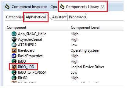
Add this component two times as we require 2 Bits for SDA and SCL interface signal
Now rename the component Bit1 IO as SDA as shown below:
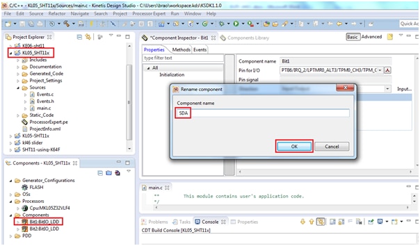
Now select the pin for I/O in our case the SDA bit is connected to PTA-9 of the freedom board
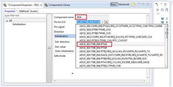
And make the other selections as shown below: make sure auto initialisation is check on.

Similarly connect Bit2 component as shown below:
Rename it as SCL and connected to PTB-13

Now add the component “Wait” as shown below:
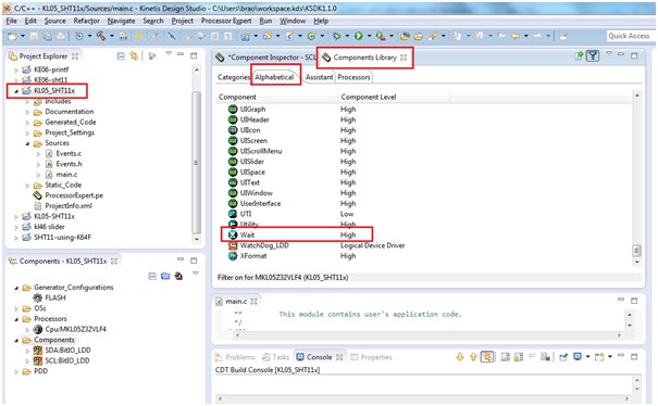
Next add the ConsoleIO component module from component library as shown below:
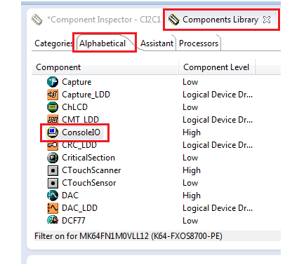
Double click on the module component to add to our project: As UART0’s RX is connected to PTB2 and UART0’s TX is connected to PTB1.
This UART port pins are required for console terminal output.
Next click on ConsoleIO_Serial_LDD button as shown below:
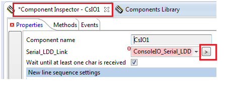
We have configured UART0 as shown below:
UART0 RxD connected to PTB-2 as shown below:
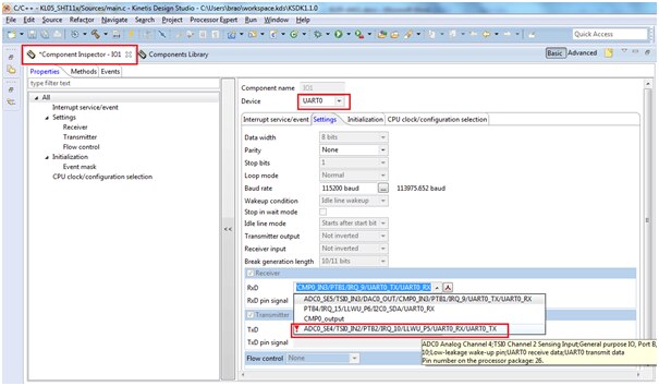
UART0 TxD connected to PTB1 as shown below:

And the baud rate is selected to 115200 as shown below:

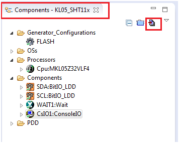
We can see all the four components added with required settings as shown below:

Now generate the project by clicking the below shown button
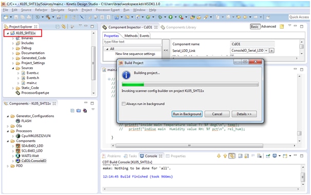
It Builds with no errors as shown below:

Now we are going to add our code in “main.c” file
int main(void)
/*lint -restore Enable MISRA rule (6.3) checking. */
{
/* Write your local variable definition here */
/*** Processor Expert internal initialization. DON'T REMOVE THIS CODE!!! ***/
PE_low_level_init();
/*** End of Processor Expert internal initialization. ***/
/* Write your code here */
/* For example: for(;;) { } */
unsigned int *p_value1, *p_value2;
SDA_Init(SDA_Ptr);
SCL_Init(SCL_Ptr);
while(1){
Read_SHT11(&temp, &rel_hum);
WAIT1_Waitms(250);
printf(" Temperature value T: %f %% degC\t", temp);
printf(" Humidity value RH: %f pct\r\n", rel_hum);
}
}
void s_transstart()
{
//Initial state
SDA_SetDir(SDA_Ptr, 0); //SDA_SetDir(SDA_Ptr, 1); //set as output// SDA_dir = 1; //release DATA-line
SDA_SetVal(SDA_Ptr); // giving high to the bit// SDA_pin = 1;
SCL_ClrVal(SCL_Ptr); // giving 0 to the bit//SCL_pin = 0; // SCL Low
WAIT1_Waitus(1); //Delay_uS(1);
SCL_SetVal(SCL_Ptr); // giving high to the bit // SCL_pin = 1;
WAIT1_Waitus(1);//Delay_uS(1);
SDA_SetDir(SDA_Ptr, 1); //set as output //SDA_dir = 0; // define SDA as output
SDA_ClrVal(SDA_Ptr); //SDA_pin = 0; // SDA low
WAIT1_Waitus(1); //Delay_uS(1);
SCL_ClrVal(SCL_Ptr); //SCL_pin = 0;
WAIT1_Waitus(3); // Delay_uS(3);
SCL_SetVal(SCL_Ptr); //SCL_pin = 1;
WAIT1_Waitus(1); //Delay_uS(1);
SDA_SetDir(SDA_Ptr, 0); //SDA_dir = 1;
WAIT1_Waitus(1); //Delay_uS(1);
SCL_ClrVal(SCL_Ptr); //SCL_pin = 0;
}
unsigned char s_read_byte(unsigned char ack)
{
unsigned char i=0x80;
unsigned char val=0;
//Initial state
SDA_SetDir(SDA_Ptr, 1); //release DATA-line
SDA_SetVal(SDA_Ptr);
SCL_ClrVal(SCL_Ptr); // SCL Low
while(i) //shift bit for masking
{
SCL_SetVal(SCL_Ptr); //clk for SENSI-BUS
SDA_SetDir(SDA_Ptr, 0); //input mode added
WAIT1_Waitus(1); // Delay_uS(1);
if (SDA_GetVal(SDA_Ptr) == 1)
{
val=(val | i); //read bit
}
SCL_ClrVal(SCL_Ptr);
WAIT1_Waitus(1); //Delay_uS(1);
i=(i>>1);
}
SDA_SetDir(SDA_Ptr, 1);
if (ack)
{
//in case of "ack==1" pull down DATA-Line
SDA_ClrVal(SDA_Ptr);
}
else
{
SDA_SetVal(SDA_Ptr);
}
SCL_SetVal(SCL_Ptr); //clk #9 for ack
WAIT1_Waitus(3); //Delay_uS(3);
SCL_ClrVal(SCL_Ptr);
WAIT1_Waitus(1); // Delay_uS(1);
SDA_SetDir(SDA_Ptr, 1); //release DATA-line
SDA_SetVal(SDA_Ptr);
return (val);
}
unsigned char s_write_byte(unsigned char value)
{
unsigned char i=0x80;
unsigned char error=0;
SDA_SetDir(SDA_Ptr, 1);
while(i)
{ //shift bit for masking
if (i & value)
{
SDA_SetVal(SDA_Ptr); //masking value with i , write to SENSI-BUS
}
else
{
SDA_ClrVal(SDA_Ptr);
}
SCL_SetVal(SCL_Ptr); //clk for SENSI-BUS
WAIT1_Waitus(3); //Delay_uS(3);
SCL_ClrVal(SCL_Ptr);
WAIT1_Waitus(3); //Delay_uS(3);
i=(i>>1);
}
SDA_SetDir(SDA_Ptr, 1); //release DATA-line
SDA_SetVal(SDA_Ptr);
SCL_SetVal(SCL_Ptr); //clk #9 for ack
WAIT1_Waitus(3); //Delay_uS(3);
SDA_SetDir(SDA_Ptr, 0); //added input mode
if (SDA_GetVal(SDA_Ptr) == 1) error = 1; //check ack (DATA will be pulled down by SHT11)
WAIT1_Waitus(1); //Delay_uS(1);
SCL_ClrVal(SCL_Ptr);
return(error); //error=1 in case of no acknowledge
}
unsigned char s_measure(unsigned int *p_value, unsigned char mode)
{
unsigned char i=0;
unsigned char msb,lsb;
unsigned char checksum;
*p_value=0;
s_transstart(); //transmission start
if(mode)
{
mode = MEASURE_HUMI;
}
else
{
mode = MEASURE_TEMP;
}
if (s_write_byte(mode)) return(1);
// normal delays: temp i=70, humi i=20
SDA_SetDir(SDA_Ptr, 0); // SDA_dir = 1;
while(i<240)
{
WAIT1_Waitms(1);
WAIT1_Waitms(1);
WAIT1_Waitms(1);
if (SDA_GetVal(SDA_Ptr) == 0)
{
i=0;
break;
}
i++;
}
// or timeout
if(i) return(2);
msb=s_read_byte(ACK); //read the first byte (MSB)
lsb=s_read_byte(ACK); //read the second byte (LSB)
checksum=s_read_byte(noACK); //read checksum (8-bit)
*p_value=(msb<<8)|(lsb);
return(0);
}
float calc_sth11_temp(unsigned int t)
{
float t_out;
t_out = t*0.01 - 40;
return t_out;
}
float calc_sth11_humi(unsigned int h, int t)
{
float rh_lin; // rh_lin: Humidity linear
float rh_true; // rh_true: Temperature compensated humidity
float t_C; // t_C : Temperature [°C]
t_C=t*0.01 - 40; //calc. temperature from ticks to [°C]
rh_lin=C3*h*h + C2*h + C1; //calc. humidity from ticks to [%RH]
rh_true=(t_C-25)*(T1+T2*h)+rh_lin; //calc. temperature compensated humidity
// now calc. Temperature compensated humidity [%RH]
// the correct formula is:
// rh_true=(t/10-25)*(0.01+0.00008*(sensor_val))+rh;
// sensor_val ~= rh*30
// we use:
// rh_true=(t/10-25) * 1/8;
if(rh_true>100)rh_true=100; //cut if the value is outside of
if(rh_true<0.1)rh_true=0.1; //the physical possible range
return rh_true;
}
void Read_SHT11(float *fT, float *fRH)
{
unsigned int t;
unsigned int h;
float value=0;
ucSens_Error = 0;
ucSens_Error = s_measure(&t, 0);
*fT = calc_sth11_temp(t);
ucSens_Error = s_measure(&h, 1);
*fRH = calc_sth11_humi(h, t);
}
char s_read_statusreg(unsigned char *p_value)
{
unsigned char checksum = 0;
s_transstart(); //transmission start
if(s_write_byte(STATUS_REG_R)) return 1; //send command to sensor
*p_value=s_read_byte(ACK); //read status register (8-bit)
checksum=s_read_byte(noACK); //read checksum (8-bit)
return 0;
}
char s_write_statusreg(unsigned char value)
{
s_transstart(); //transmission start
if(s_write_byte(STATUS_REG_W)) return 1; //send command to sensor
if(s_write_byte(value)) return 1; //send value of status register
return 0;
}
void s_connectionreset()
{
unsigned char i;
//Initial state
SDA_SetDir(SDA_Ptr, 1); //release DATA-line
SDA_SetVal(SDA_Ptr);
SCL_ClrVal(SCL_Ptr); // SCL Low
for(i=0; i<9; i++) //9 SCK cycles
{
SCL_SetVal(SCL_Ptr);
WAIT1_Waitus(3);
SCL_ClrVal(SCL_Ptr);
WAIT1_Waitus(3);
}
s_transstart(); //transmission start
}
unsigned char s_softreset(void)
{
s_connectionreset(); //reset communication
//send RESET-command to sensor
return (s_write_byte(RESET)); //return=1 in case of no response form the sensor
}
Explanation of code:
The below are the function/driver required for this code:
- void s_transstart()
- unsigned char s_read_byte(unsigned char ack)
- unsigned char s_write_byte(unsigned char value)
- unsigned char s_measure(unsigned int *p_value, unsigned char mode)
- float calc_sth11_temp(unsigned int t)
- float calc_sth11_humi(unsigned int h, int t)
- void Read_SHT11(float *fT, float *fRH)
- char s_read_statusreg(unsigned char *p_value)
- char s_write_statusreg(unsigned char value)
- void s_connectionreset()
- unsigned char s_softreset(void)
Inside main we are calling the function Read_SHT11() which in turn returns the temperature and humidity values
The function “calc_sth11_temp()” will generate the required I2C signals by Bit Banging method i.e it simulates the signal without using the internal resource.
and gives you the temperature value.
The function ”calc_sth11_humi()” will generate the necessary I2C signal (Bit Banging) and get the humidity value.
For more details on timing signal refer to the SHT11 datasheet:
Note: as we are printing floating point sensor data we need to set up KDS to print floating numbers
Right click on project folder and select the properties and do the settings as shown below:
We need to add “-nanolibc -u _printf_float” in “Tool settings” as shown below:

Now it’s time to build the project, click on the hammer button as shown

You can see the build is finished successfully with no errors
Now it is ready to debug/execute
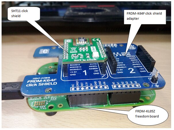
Now connect the KL05Z board to OPEN SDA port to your computer through USB cable. The hardware setup is as shown below, the click board is connected via click shield
Make sure you have downloaded the OpenSDA debug driver for the FRDM-KL05Z board
“MSD-DEBUG-FRDM-KL05Z_Pemicro_v114.SDA”
(you can download the driver from PE micro website link: http://www.pemicro.com/opensda/index.cfm)
Now configure for debugging the project:

Click on Debug configuration as shown below:

Now click on Apply and Debug
You can see below Debug window screen

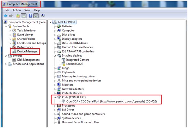
Identify your hyperterminal port umber from Device manager as shown below:
In my case it is connected to COM52 port
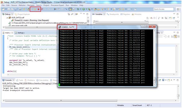
Now open hyperterminal window of your choice, i am opening it from putty terminal

Now click on green ‘Resume’ button

The output seen in the terminal is as shown below:
I have enclosed the *.SREC file, you can download this and test it directly by programming the binaries.
And also the project folder for your quick reference.
Happy SHT11 click interfacing on KL05Z 
