


Here is a tutorial for toggling RGB Led’s on FRDM-KL27Z board using Kinetis Design Studio IDE and using Kinetis Software development kit (KSDK).
Before we begin make sure below requirements are there as setup
Required Hardware and Software:
- FRDM-KL27Z Board loaded with MSD OpenSDA driver
(The firmware can be downloaded from FRDM-KL27-QSP)
- Micro USB Cable
- Kinetis Design Studio (v2.0.0)
(http://www.freescale.com/webapp/sps/site/prod_summary.jsp?code=KDS_IDE)
- Kinetis Software Development Kit for KL27Z (KSDK-v1.1.0)
(Download Link Kinetis SDK1.1.0 Standalone for the FRDM-KL27Z - Windows Installer )
Please refer to my blog for below actions: which was created earlier “Toggling LED without using Processor expert”
Installing Kinetis SDK1.1.0 for KL27Z
Eclipse Update for Kinetis SDK1.1.0 (KL27Z)
Build the platform driver library
Creating New Project:
So let’s start in creating a new project using KDS + KSDK IDE
Open KDS IDE by double clicking the KDS icon present in your desktop:
It will ask for the Workspace, give the path of your choice and click ‘ok’

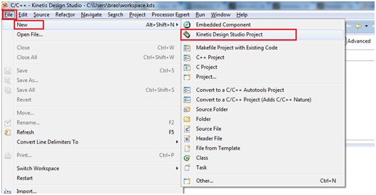
Next create a New project by clicking
File -> New -> Kinetis Design Studio Project
Choose project name of your choice, i have given it as “KL27-LED-SDK-PE” and click Next.

You can select device either by ‘Boards’ or ‘Processor’ option, I am selecting the target device by processors as shown below:

You can see the Device part number of “MKL27Z64xxx4” click on “Next”
In the next screen you can find below options to be selected in Rapid Application Development window
Select the check box “Kinetis SDK”
And select the radio button “Absolute path” and browse for installed KSDK for KL27Z directory as shown below:

Proceed further and select the processor expert check box as below:

Next click Finish button and proceed further.
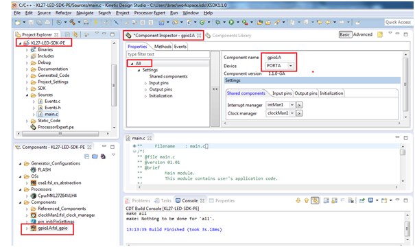
The project has been created with processor expert options included (i.e component window) and the project window looks like as shown below:

Next we need to add the component for gpio functionalities,
Select fsl_gpio from component library as shown:

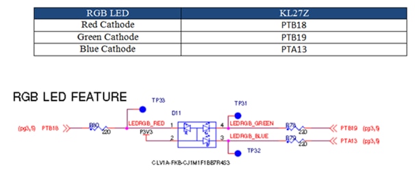
As we know the LED’s have been connected to the board as shown below:
Click on fsl_gpio component to assign the 3 port pins as output connected to Led
Next select on Output pins > Output configurations option and press on ‘+’ button to increase the output pin numbers

Now select the first configuration and change the port pin setting to PTB-18 connected to Red LED, Rename this as ‘GPIOB18Red’

Similarly make the settings for the second one connected to PTB-19 port pin which is Green LED. Rename it as ‘GPIOB19Green’
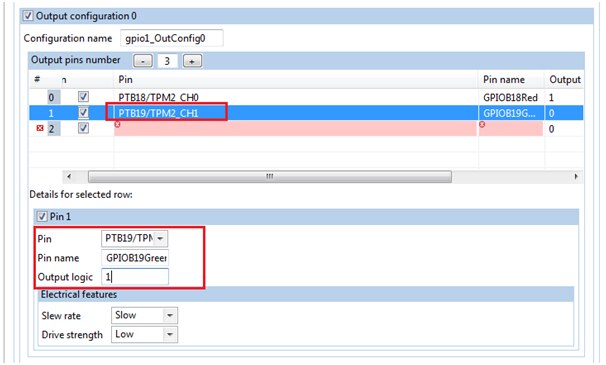
We are assigning PTA13 for blue led and make the below settings:
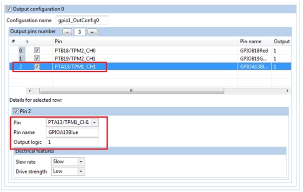
In all the three settings we have assigned Output logic = 1 (since LED is active Low connection)
Next click on Input configuration option and deselect the check box as shown below:

Next click on initialization and deselect the input pin option check box as shown below

Now add the component wait() which is used to insert some delay routines in our program

As our project creation is by using processor expert we need not have to add any board related header folders to the project, those all required files are been taken care by processor expert itself.
These files have been generated in “Generated_Code” folder as shown below

Now to ensure our project is created without errors we will build it once

It builds with no error
Now we will proceed further by adding our code to toggle these led’s
You can see these LED’s are connected in active-Low connection, i.e common Anode, we should provide Low signal to port pins to glow a LED.
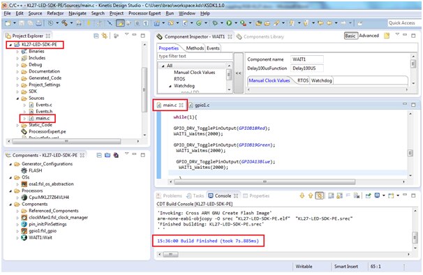
LED’s have been defined in the file called gpio1.c as shown below:

Now we shall toggle all the 3 LED’s one by one with some software delay() i.e blue is on for some time then blue+red is on for some time then blue+red+green is on for some time, this is one cycle of toggling pins and next time reverse happens i.e red+green is on (blue = off) and green is on (blue, red = off) then green also off (all the 3 led’s are off) this sequence loops back.
Navigate to fsl_gpio component and select GPIO_DRV_TogglePinOutput(); drag this function towards main.c and leave it to the shown position inside main();

Now we need to add the parameter for this function.
The parameter can be any of the led defined inside gpio.c
Below is my line of code to do this task
#include"Cpu.h"
#include "Events.h"
#include "pin_init.h"
#include "osa1.h"
#include "gpio1.h"
#include "WAIT1.h"
#if CPU_INIT_CONFIG
#include "Init_Config.h"
#endif
/* User includes (#include below this line is not maintained by Processor Expert) */
/*lint -save -e970 Disable MISRA rule (6.3) checking. */
int main(void)
/*lint -restore Enable MISRA rule (6.3) checking. */
{
/* Write your local variable definition here */
/*** Processor Expert internal initialization. DON'T REMOVE THIS CODE!!! ***/
PE_low_level_init();
/*** End of Processor Expert internal initialization. ***/
/* Write your code here */
/* For example: for(;;) { } */
while(1){
GPIO_DRV_TogglePinOutput(GPIOB18Red);
WAIT1_Waitms(2000);
GPIO_DRV_TogglePinOutput(GPIOB19Green);
WAIT1_Waitms(2000);
GPIO_DRV_TogglePinOutput(GPIOA13Blue);
WAIT1_Waitms(2000);
}
/*** Don't write any code pass this line, or it will be deleted during code generation. ***/
/*** RTOS startup code. Macro PEX_RTOS_START is defined by the RTOS component. DON'T MODIFY THIS CODE!!! ***/
#ifdef PEX_RTOS_START
PEX_RTOS_START(); /* Startup of the selected RTOS. Macro is defined by the RTOS component. */
#endif
/*** End of RTOS startup code. ***/
/*** Processor Expert end of main routine. DON'T MODIFY THIS CODE!!! ***/
for(;;){}
/*** Processor Expert end of main routine. DON'T WRITE CODE BELOW!!! ***/
} /*** End of main routine. DO NOT MODIFY THIS TEXT!!! ***/
/* END main */
Explanation of the code:
GPIO_DRV_TogglePinOutput(GPIOB18Red);
This function toggles the red led and waits for 2 seconds as given in wait() function
WAIT1_Waitms(2000);
Similarly the case for the Green and Blue led
while(1){
GPIO_DRV_TogglePinOutput(GPIOB18Red);
WAIT1_Waitms(2000);
GPIO_DRV_TogglePinOutput(GPIOB19Green);
WAIT1_Waitms(2000);
GPIO_DRV_TogglePinOutput(GPIOA13Blue);
WAIT1_Waitms(2000);
}
Inside the while() loop the led’s are been toggled one by one with delay
Now it’s time to clean and compile/Build the project

You can see the build output as shown below:
Now we need to setup for Debug configuration:
As a pre-requisite the board is loaded with OpenSDA provided in “FRDM-KL27-QSP.zip”

Select ‘GDB PEMicro interface Debugging’ and double click or right click and select ‘New’
You can see a default name as project name as shown below: make sure under ‘Main’ tab C/C++ application there is *.elf file name of your project.

Next click on Debugger tab check the interface is selected to OpenSDA and port is assigned as shown below
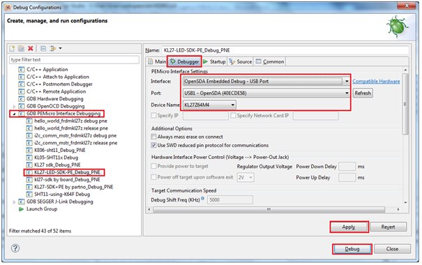
(make sure you have connected the board to PC via USB mini connector to “Open SDA” J-13 jumper of the board)
Now you can see the Debug window opens ready for single stepping or Running the project as shown:

Click on Resume button or press ‘F8’ button for executing the project.
You can see the output as shown
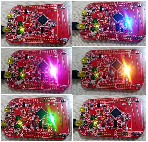
Attached is the video recording of the project execution.
And i have enclosed the project folder for quick view and execution.
And also you can directly check the execution by programming the *.srec file to the board
Happy Toggling 