


Here is a tutorial for toggling RGB Led’s on FRDM-KL27Z board using Kinetis Design Studio IDE and using Kinetis Software development kit (KSDK).
Before we begin make sure below requirements are there as setup.
Required Hardware and Software:
1. FRDM-KL27Z Board loaded with MSD OpenSDA driver
(The firmware can be downloaded from FRDM-KL27-QSP)
2. Micro USB Cable
3. Kinetis Design Studio (v2.0.0)
(http://www.freescale.com/webapp/sps/site/prod_summary.jsp?code=KDS_IDE)
4. Kinetis Software Development Kit for KL27Z (KSDK-v1.1.0)
(Download Link Kinetis SDK1.1.0 Standalone for the FRDM-KL27Z - Windows Installer )
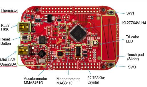
The features of the FRDM-KL27Z board are:
- KL27Z64VLH4 MCU (48 MHz, 64 KB Flash, 16 KB RAM, low power, 64 LQFP package)
- Capacitive touch slider, accelerometer MMA8451Q, Magnetometer MAG3110 ,Tri-color LED
- Flexible power supply options – USB, coin cell battery, external source
- Easy access to MCU I/O
- Tri-color user‐controllable LEDs
- Two (2) user push-button switches for NMI interrupts and LLWU wake up (SW1/SW3)
- Thermistor sensor to measure temperature
- Battery-ready, power-measurement access points
- Form factor compatible with Arduino
 R3 pin layout
 - New OpenSDA debug interface:
- Mass storage device flash programming interface by default. No tool installation is required to evaluate demo applications.
- P&E Micro Debug interface provides run-control debugging and compatibility with IDE tools.
Installing Kinetis SDK1.1.0 for KL27Z
First we need to install the Kinetis SDK1.1.0 standalone for FRDM-KL27Z freedom board. Below is the link to install.
Kinetis SDK1.1.0 Standalone for the FRDM-KL27Z - Windows Installer
It has been installed in below folder in my case:
C:\Freescale\KSDK1.1.0_KL27Z_1.0.0
Eclipse Update for Kinetis SDK1.1.0 (KL27Z)
Click on Help > Install New Software as shown below:

Click on Add as shown below

Next select Archive

Provide your path to the already installed directory
C:\Freescale\KSDK1.1.0_KL27Z_1.0.0\tools\eclipse_update
Select “KSDK_1.1.0_KLx7Z_Eclipse_Update.zip” as shown below

Click on “Open”, and then “OK” in the “Add Repository” dialog box.
Check the box to the left of the KSDK Eclipse update and click “Next” in the lower right corner. Follow the remaining instructions to finish the installation of the update.
Once the update is applied, restart KDS for the changes to take effect.
Build the platform driver library
Before building and debugging any demo application in KSDK, the driver library project should be built to generate the library archives: ksdk_platform_lib.a. Because this library contains all binary codes for HAL and the peripheral drivers specific to the chip, each SoC has its own platform.a library archives.
Now we will proceed further building platform library
We need to Importing platform library from the KSDK installation path and build the library, follow below steps to import and build the platform library.
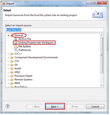
Open the KDS IDE by giving your default workspace and select ‘import’ option as shown below:
Select File>Import

Next select the option “Existing projects into Workspace” from General Tab and click “Next”
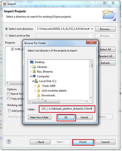
Click on “Browse” button as shown below:

Browse to navigate to KSDK1.1.0 installation folder and select the path as shown below
“C:\Freescale\KSDK1.1.0_KL27Z_1.0.0\lib\ksdk_platform_lib\kds\KL27Z644”
Now select the Project, right click, clean and build the project as shown below:


You can see the build progress / status in console window, if everything goes well you can see build finishes as shown:
When the build is complete, the ‘libksdk_platform.a’ is generated in the directory according to the build target which is located here
“C:\Freescale\KSDK1.1.0_KL27Z_1.0.0\lib\ksdk_platform_lib\kds\KL27Z644\Debug\ libksdk_platform.a”
We need to provide this path in our new project in "Cross ARM C++ Linker" option to add the KSDK library in the compiler. (this will be shown later while creating new project)
Creating New Project:
So let’s start in creating a new project using KDS + KSDK IDE
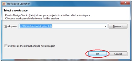
Open KDS IDE by double clicking the KDS icon present in your desktop:
It will ask for the Workspace, give the path of your choice and click ‘ok’
Next create a New project by clicking
File -> New -> Kinetis Design Studio Project

Choose project name of your choice, i have given it as “K64-LED Blink-KSDK” and click Next.

You can select device either by ‘Boards’ or ‘Processor’ option, I am selecting the target device by processors as shown below:

You can see the Device part number of “MKL27Z64xxx4” click on “Next”
In the next screen you can find below options to be selected in Rapid Application Development window
Select the check box “Kinetis SDK”
And select the radio button “Absolute path” and browse for installed KSDK for KL27Z directory as shown below:

Provide the installed KSDK path i.e “C:\Freescale\KSDK1.1.0_KL27Z_1.0.0” then proceed further

Click finish to proceed further.
Now our created project platform is ready, You can see a KDS project window created for our New project.

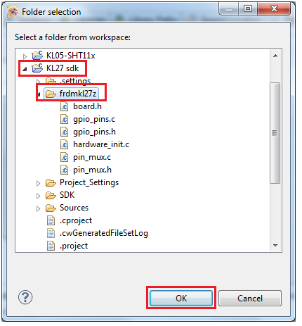
It is necessary to include the required ‘board’ folder for this project. To add it right click on the project just created and chose "Import".

Select the “File System” and click on Next as shown below:

Now look for the board folder in the installed KSDK1.1.0 folder
C:\Freescale\KSDK1.1.0_KL27Z_1.0.0\boards\frdmkl27z as shown below:
Select only *.c and *.h files from option as shown below and proceed to Finish.

You can see the board header folder “frdmkl27z” is added to our project folder as shown:

We need to add the “boards.h” folder path to the project settings, it is done as shown below:

Now select our workspace path and the frdmkl27z folder which contains our board related header files:
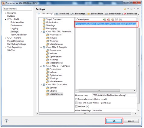
Next we need to add the KSDK library in the compiler, this step is very important else u will not be able to compile your project.
To add this you need to right click the project and click in "Properties".
select "C/C++ Build" > "Settings".
Then click on “Tool Settings” and select "Miscellaneous" under "Cross ARM C++ Linker" option as shown below:

Click on add object button as shown above and add the library here. 
The default path is
“C:\Freescale\KSDK1.1.0_KL27Z_1.0.0\lib\ksdk_platform_lib\kds\KL27Z644\Debug\libksdk_platform.a”

And proceed further
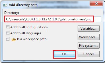
Make sure the compiler knows the include path to the boards folder. As the board files are using a bunch of other include files of the SDK, I need to add some extra compiler include paths:
We have to add these include paths in ‘properties’ > ‘C/C++ General’ > ‘Paths and Symbols’ as shown and add the paths
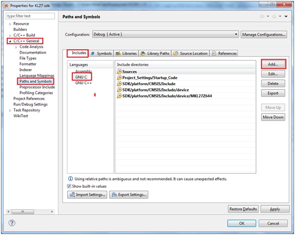
The include files and corresponding paths to be provided are as given below:
File: fsl_gpio_driver.h
Path to be added C:\Freescale\KSDK1.1.0_KL27Z_1.0.0\platform\drivers\inc
Similarly for the other include file paths as below
File: fsl_port_hal.h
Path to be added C:\Freescale\KSDK1.1.0_KL27Z_1.0.0\platform\hal\inc
File: fsl_clock_manager.h
Path to be added C:\Freescale\KSDK1.1.0_KL27Z_1.0.0\platform\system\inc
File: fsl_debug_console.h
Path to be added C:\Freescale\KSDK1.1.0_KL27Z_1.0.0\platform\utilities\inc
File: fsl_os_abstraction.h
Path to be added C:\Freescale\KSDK1.1.0_KL27Z_1.0.0\platform\osa\inc

With this, I’m able to compile and link the board file
It builds with no error

Now our platform is ready and we need to write our code to toggle the RGB
It is necessary to include the boards.h file:
#include "board.h"
We are now proceeding further in coding our requirement to toggle RGB LEDs.
Refer to the board schematic the 3 LED’s are connected to Port-B and Port-A pins

You can see these LED’s are connected in active-Low connection, i.e common Anode, we should provide Low signal to port pins to glow a LED.
Led’s have been defined in board.h file
#define BOARD_GPIO_LED_RED kGpioLED2
#define BOARD_GPIO_LED_GREEN kGpioLED3
#define BOARD_GPIO_LED_BLUE kGpioLED1
To know how GPIO have been defined in KSDK library click on include folder and navigate to /platform/drivers/inc
and select ‘fsl_gpio_driver.h’ as shown below:

By default kGpioLED1, kGpioLED2, kGpioLED3 have been already defined in library,
Now we shall toggle all the 3 LED’s one by one with some software delay() i.e blue is on for some time then blue+red is on for some time then blue+red+green is on for some time, this is one cycle of toggling pins and next time reverse happens i.e red+green is on (blue = off) and green is on (blue, red = off) then green also off (all the 3 led’s are off) this sequence loops back.
Below is my line of code to do this task
#include<stdio.h>
#include<stdlib.h>
#include"fsl_device_registers.h"
#include"fsl_debug_console.h"
#include"board.h"
#include"fsl_lpuart_hal.h"
staticint i = 0;
//void dbg_uart_init();
int main(void)
{
/* Write your code here */
hardware_init();
GPIO_DRV_SetPinDir(kGpioLED1,kGpioDigitalOutput); // kGpioDigitalOutput = 1=output
GPIO_DRV_SetPinOutput(kGpioLED1); //set pin = led off
GPIO_DRV_SetPinDir(kGpioLED2,kGpioDigitalOutput); // kGpioDigitalOutput = 1=output
GPIO_DRV_SetPinOutput(kGpioLED2); //set pin = led off
GPIO_DRV_SetPinDir(kGpioLED3,kGpioDigitalOutput); // kGpioDigitalOutput = 1=output
GPIO_DRV_SetPinOutput(kGpioLED3); //set pin = led off
/* This for loop should be replaced. By default this loop allows a single stepping. */
for (;;) {
GPIO_DRV_TogglePinOutput(kGpioLED1); // Toggle LED1=Blue
for (i = 0; i<10000000; i++); // software delay
GPIO_DRV_TogglePinOutput(kGpioLED2); // Toggle LED2=Red
for (i = 0; i<10000000; i++); // software delay
GPIO_DRV_TogglePinOutput(kGpioLED3); // Toggle LED3=Green
for (i = 0; i<10000000; i++); // software delay
}
/* Never leave main */
return 0;
}
////////////////////////////////////////////////////////////////////////////////
// EOF
////////////////////////////////////////////////////////////////////////////////
Explanation of the code:
Configuring the Port pin
GPIO_DRV_SetPinDir(kGpioLED1, kGpioDigitalOutput); // kGpioDigitalOutput = 1=output
This function configures the kGpioLED1 pin as digital output and by default this will be pull down to GND (i.e port pin driven to zero)
GPIO_DRV_SetPinOutput(kGpioLED1); //set pin = led off
This function sets /writes pin kGpioLED1 to ‘1’ which means the LED is in off condition.
Same thing is done for other 2 port led’s
Next in the infinite for loop we are toggling each pin sequentially with software delay();
for (;;) {
GPIO_DRV_TogglePinOutput(kGpioLED1); // Toggle LED1=Blue
for (i = 0; i<10000000; i++); // software delay
GPIO_DRV_TogglePinOutput(kGpioLED2); // Toggle LED2=Red
for (i = 0; i<10000000; i++); // software delay
GPIO_DRV_TogglePinOutput(kGpioLED3); // Toggle LED3=Green
for (i = 0; i<10000000; i++); // software delay
}
Now it’s time to clean and compile/Build the project

You can see the build output as shown below:

Now we need to setup for Debug configuration:
As a pre-requisite the board is loaded with OpenSDA provided in “FRDM-KL27-QSP.zip”

Select ‘GDB PEMicro interface Debugging’ and double click or right click and select ‘New’
You can see a default name as project name as shown below: make sure under ‘Main’ tab C/C++ application there is *.elf file name of your project.

Next click on Debugger tab check the interface is selected to OpenSDA and port is assigned as shown below

(make sure you have connected the board to PC via USB mini connector to “Open SDA” J-13 jumper of the board)
Now you can see the Debug window opens ready for single stepping or Running the project as shown:

Click on Resume button or press ‘F8’ button for executing the project.
You can see the output as shown

Attached is the video recording of the project execution.
And i have enclosed the project folder and SREC file for quick view and execution.
Happy Toggling 
Top Comments