


This tutorial brings you on getting working with 4-digit (4X8) segment LCD present in KL46Z freedom board.
We will use the Freescale Codewarrior for MCU toolchain, which integrates the Processor Expert code generator tool.
A free Codewarrior editions either Special (code size limited to 64KB) or Evaluation (30 days limited) are downloadable from Freescale website
Launch Freescale Codewarrior for MCU and create a new project for KL46Z board following below procedure (refer to the blog link for “how to create project using processor expert” )
- In the CodeWarrior, click File menu and select New > Bareboard Project in order to create a new project. The Project Wizard appears. Enter the name of the project "LCD seg-seg kl46" and click Next.
- Now select the MCU available on our KL46 board which is the MKL46Z256
Kinetis L Series ⇒ KL4x Family ⇒ KL46Z(48 MHz) Family ⇒ MKL46Z256 then Click Next.
- Select OpenSDA connection for debugging and programming, then click Next.
- Keep the Language and Build Tools Options unchanged and click Next.
Select Processor Expert option as we are creating the project using Processor Expert, then click Finish
A new project named "LCD seg-seg kl46" is created as shown below. The Component Inspector view for the CPU should be automatically opened with default settings (else double click on the CPU in the Components view):

First we need to define CPU parameter as below:

Under Clock settings (expand the Clock settings by clicking on the white arrow)
System Oscillator: Enabled
Clock Source: External Oscillator (default)
Clock Frequency: 8 MHz (default) (KL46 is connected to an external crystal oscillator on the FRDM-KL46Z)
Clock source settings ⇒ Clock source settings 0
MCG settings ⇒ MCG mode: FEI (FLL engaged internal)
FLL settings ⇒ FLL output [MHz]: 47.972352
MCG output[MHz] will automatically updates to 47.972352
Under Clock configurations ⇒ Clock configuration 0 ⇒ System clocks set
Core clock: 47.972352 MHz
Bus clock: 23.986176 MHz
All the other parameters previously highlighted in RED should be automatically updated and turned black/grey, which means that all the CPU settings are now correct. In the Components window a green tick will appear on the CPU symbol if everything went fine.
 Since now our project skeleton is ready (i.e no component module peripherals has been added to our project), we need now to add the required peripheral component modules for our LCD project.
We will add first two component modules to blink the red and the green LEDs of the FRDM-KL46Z
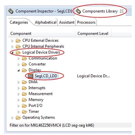
Open the Components Library view and select the Categories tab
Expand the Logical Device Drivers ⇒ Port I/O and select the BitIO_LDD component
Right click and select Add to Project twice, since we need two LED components in our project (one per LED).

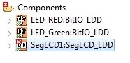
Rename the components (LED_RED, LED_Green) as shown below:
Right click on the corresponding module in the Components view and select Rename Component

According to the board schematics, Red LED is connected to Port PTE29 and Green LED is connected to Port PTD5 of the MKL46Z256VLL4 MCU.

Select the corresponding module in the Component view and switch to the Components Inspector view to make change the Pin for I/O as below:
LED_RED BitIO assigned to the output pin PTE29
Init. value must be set to 1
Auto initialization must be defined to yes
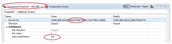
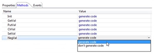
In the Methods tab, select NegVal Generate code

LED_Green BitIO assigned to the output pin PTD5
Init. value must be set to 1
Auto initialization must be defined to yes
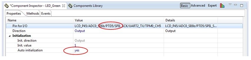
In the Methods tab, select NegVal Generate code
Introduction to set up the Segment LCD controller
Segment LCD modules are simple and very low power LCD displays. They can have a large number of segments in the form of dots (pixels) or symbols (parts of 7 segment characters or special images) and a large number of pins to enable these segments to be controlled. SLCD controllers tend to have a high number of pins to handle large GLCD modules. These pins can be configured as back-plane or front-plane pins and generates the required multiplexing and waveforms needed to continuously refresh the SLCD.
Rather than have one connection for each segment, the segments are typically multiplexed so that less control lines are needed to control the same number of individual segments.
To illustrate this, the Lumex LCD-S401M16KR, as used on the Freescale FRDM-KL46Z is used as reference. The following is an excerpt from its data sheet showing its characteristics and how its 12 pins are connected to its elements:
Characteristics of Lumex LCD-S401M16KR are given below:

Connection details of Luminex LCD-S401M16KR

And the display’s elements are illustrated below according to their references in the Connection table in the original data sheet:

s401 segments layout
This display has 12 pins, which are all connected to a driving pin on the SLCD controller. There are 4 common pins and so the driving mode is ¼ duty cycle, since each of the common pins are driven for ¼ of the cycle period. Each of the common lines is connected to 8 LCD segments. Taking COM0 as an example the 8 segments that are controlled by it are show in the following diagram.

This means that when the COM0 line is being driven up to 8 segments can be turned on, depending on the state of the 8 segment pins. The 8 segment pins (5..12) thus control these 8 segments during this driving phase and can turn all on, all off, or an combination in between.
Since there are 4 phases (4 COM pins), each controlling 8 segments during that phase, a total of 32 segments can be controlled – this corresponds to the number of segments that the SLCD physically has. The other 3 COM drive combinations are not shown in a diagram here but can be easily read from the original data sheet table.
In order to configure the SLCD driver to match this display 4 of its LCD pins are configured as COM drive pins and 8 as segment drive pins. The COM drive pins are configured to drive in different phases (eg. COM0 in phase 1, COM1 in phase 2, COM2 in phase 3 and COM3 in phase 4, where each of the phases are repeated according to ¼ duty driving mode). The duty mode and any other specific configuration are also set in the SLCD controller.
Now we need to add a LCD component available in Processor Expert to operate the LCD screen embedded on the board.
FRDM-KL46Z is using a 4 digit display (LUMEX LCD-S401M16KR) 4x8 segments. Following table shows connection from KL46 board to s401 LCD display and same configuration need to be assigned to the port pins.

Select in the Components Library view the LCD module available in Component Library ⇒ Logical Device Driver ⇒ Display⇒ SegLCD_LDD
and add it to project by double clicking as shown below:
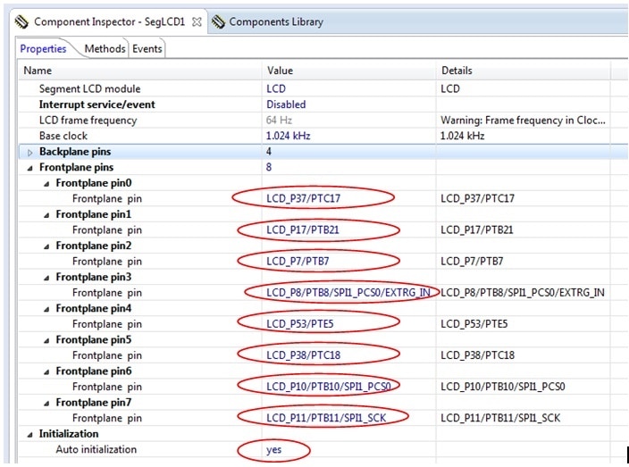
Select the SegLCD1:SegLCD_LDD in the Components view and switch to the Component Inspect view to enter the parameter (a red cross on the component module indicates that parameters are missing)
Base clock must be defined as 1.024kHz
Click on the

A new window will appear with Possible settings
Double click on the 1.024kHz and press OK to fill-in the field in the Component Inspector window.
LCD component has Backplane pins and Frontplane pins, as there are 4 Backplane pins, which are common pins connected to LCD com0, com1, com2, com3 pins.
Increase Backplane pins up to 4 by clicking on the +
Expand the Backplane pins menu by clicking on the white arrow and assign corresponding port pins (refer to the KL46 LCD Pin
table mentioned earlier) to the Backplane pins:
Backplane pin0 / Backplane pin ⇒ LCD_P40
Backplane pin 1 / Backplane pin ⇒ LCD_P52
Backplane pin 2 / Backplane pin ⇒ LCD_P19
Backplane pin 2 / Backplane pin ⇒ LCD_P18

Increase Frontplane pins up to 8 by clicking on the +
Now similarly, expand the Frontplane pins menu by clicking on the white arrow to define the 8 segment pins corresponding to the Frontplane pins in Processor Expert with following assignments:
Frontplane pin0 / Frontplane pin ⇒ LCD_P37
Frontplane pin1 / Frontplane pin ⇒ LCD_P17
Frontplane pin2 / Frontplane pin ⇒ LCD_P7
Frontplane pin3 / Frontplane pin ⇒ LCD_P8
Frontplane pin4 / Frontplane pin ⇒ LCD_P53
Frontplane pin5 / Frontplane pin ⇒ LCD_P38
Frontplane pin6 / Frontplane pin ⇒ LCD_P10
Frontplane pin7 / Frontplane pin ⇒ LCD_P11
Auto initialization must be defined to yes
If you followed carefully the instructions above you should get a green tick on the SegLCD1:SegLCD_LDD component in the Components view of your project.

Now we have added one LCD module and two LED modules as required for this demonstration and shown below:

Software drivers are required for communication between LCD controller and LCD screen and manage the display. You can write your own driver or use Freescale existing drivers.
To get the Freescale LCD drivers, simply download the Sample Code Package KL46Z_sc.exe from the FRDM-KL46Z product page in the download tab.
You will find a LCD folder following the path kl46_sc_rev3\src\projects\FRDMKL46_Demo\ which contains *.C files and *.h files as shown below:
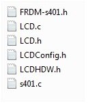
Copy this LCD folder and paste in the Codewarrior Projects view in the Sources folder as shown below:

Now our all the components and drivers are ready for the next step.
Click on Generate Processor Expert code radio button as shown below

You can see the tool generates required code as shown below:

All the required header files will get generated under ‘Generated_Code’
Next open the main.c file available in the Sources folder from the "LCD seg-seg kl46" Codewarrior Project view and write/paste the below lines of code:
/* Including needed modules to compile this module/procedure */
#include "Cpu.h"
#include "Events.h"
#include "SegLCD1.h"
#include "LED_GREEN.h"
#include "LED_RED.h"
#include "BitIoLdd1.h"
#include "BitIoLdd2.h"
/* Including shared modules, which are used for whole project */
#include "PE_Types.h"
#include "PE_Error.h"
#include "PE_Const.h"
#include "IO_Map.h"
#include "LCD.h"
#include "cstdio"
#define CW
/* variables */
LDD_TDeviceData *MySegLCDPtr, RED, Green;
char seg[]={7,8,10,11,17,37,38,53}; // seven segment connection
char col[]={0,1,2,3}; //column of lcd
char sLCDBuffer[16]; //temporal buffer for the sLCD,
int main_counter,i,j;
/* User includes (#include below this line is not maintained by Processor Expert) */
int main(void)
{
/* Write your local variable definition here */
/*** Processor Expert internal initialization. DON'T REMOVE THIS CODE!!! ***/
PE_low_level_init();
/*** End of Processor Expert internal initialization. ***/
MySegLCDPtr = SegLCD1_Init(NULL); //initialize sLCD according to PEx
RED = RED_Init(NULL); //initialize RED LED according to PEx
Green = Green_Init(NULL); //initialize Green LED according to PEx
for(;;)
{
for(j=0;j<=7;j++){
for(i=0;i<=3;i++){
SymbolON(seg[j],i);
for (main_counter=1000000 ; main_counter>0 ;main_counter--){}; //delay
//SymbolOFF(seg[0],i);
}
}
vfnLCD_All_Segments_OFF(); // all segments are turned-off
for(i=0;i<=9999;i=i+1111){
sprintf(sLCDBuffer,"%04i",i);
vfnLCD_Write_Msg((uint8 *)sLCDBuffer);
for (main_counter=1000000 ; main_counter>0 ;main_counter--){};
Green_NegVal(Green);
RED_NegVal(RED);}
vfnLCD_All_Segments_OFF();
}
/*** Don't write any code pass this line, or it will be deleted during code generation. ***/
/*** RTOS startup code. Macro PEX_RTOS_START is defined by the RTOS component. DON'T MODIFY THIS CODE!!! ***/
#ifdef PEX_RTOS_START
PEX_RTOS_START(); /* Startup of the selected RTOS. Macro is defined by the RTOS component. */
#endif
/*** End of RTOS startup code. ***/
/*** Processor Expert end of main routine. DON'T MODIFY THIS CODE!!! ***/
for(;;){}
/*** Processor Expert end of main routine. DON'T WRITE CODE BELOW!!! ***/
} /*** End of main routine. DO NOT MODIFY THIS TEXT!!! ***/
/* END ProcessorExpert */
/*!
** @}
*/
/*
**
###################################################################
In our demonstration program we are glowing each segment of LCD one by one (all the 32 segments) and display the numbers 0-9 on all the digits of LCD.
Explaination of code:
char seg[]={7,8,10,11,17,37,38,53}; // seven segment connection
char col[]={0,1,2,3}; //column of lcd
Here we have defined two char array one for segment and other for common pins of LCD
The array seg[] represents the assigned hardware connection in our LCD component configuration the segments of LCD to port pins.
Array Col[] represents the common pins of LCD
To turn on the particular segment we have the macro “SymbolON(LCDn,bit)” defined in “LCDConfig.h” file present in LCD driver folder
#define SymbolON(LCDn,bit) *((uint8 *)&LCD_WF_BASE + LCDn) |= (1<<(bit))
#define SymbolOFF(LCDn,bit) *((uint8 *)&LCD_WF_BASE + LCDn) &= ~(1<<(bit))
So we are using this macro in our program to turn all the segments one-by-one
for(j=0;j<=7;j++){
for(i=0;i<=3;i++){
SymbolON(seg[j],i); //Macro to turn on the segment of LCD
for (main_counter=1000000 ; main_counter>0 ;main_counter--){}; //delay
//SymbolOFF(seg[0],i); // Macro to turn off the segments of LCD
}
}
Now to display the numbers from 0-9 on all the digits simultaneously we have below lines of codes. also while displaying the digits the Red and Green LED's will toggle on every count.
for(i=0;i<=9999;i=i+1111){
sprintf(sLCDBuffer,"%04i",i);
vfnLCD_Write_Msg((uint8 *)sLCDBuffer); //
for (main_counter=1000000 ; main_counter>0 ;main_counter--){};
Green_NegVal(Green);
RED_NegVal(RED);
}
vfnLCD_Write_Msg((uint8 *)sLCDBuffer)writes the character to digits of LCD this function is defined in LCD.c file in driver.
sprintf(sLCDBuffer,"%04i",i)is writing the integer value ‘i’ into char buffer sLCDBuffer array and ‘%04i’ is limiting the buffer value display to 4-digits
for toggling the LED's below line of code corresponding to led components has been used:
LED_GREEN_NegVal(); //toogles the Green LED
LED_RED_NegVal(); //toogles the Red LED
We will now test the project on the FRDM-KL46Z board.
First save the project selecting File ⇒ Save All
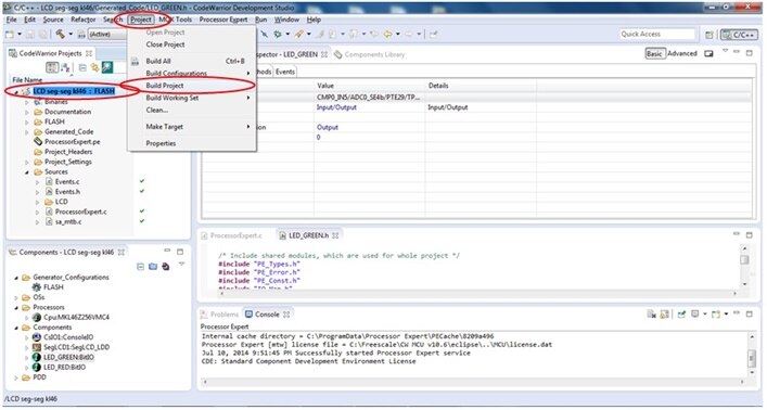
Compile the project using Project ⇒Build All or clicking on the icon available in the toolbar.
Before launching the debug session, you need to setup your FRDM-KL46Z with the OpenSDA P&E Debug interface.
To ensure a proper detection, download the P&E Windows USB drivers available at www.pemicro.com/opensda and install it. At the same time download the P&E Firmware Apps package.
Keep the Reset button while connecting the USB cable to SDA Connector (bottom one below) to enter in Bootloader mode.
From your file explorer drag’n drop or copy-paste in the BOOTLOADER drive the configuration file MSD-DEBUG-FRDM-KL46Z48M_Pemicro_v114.SDA available in the P&E Firmware Apps package.
Unplug and replug the USB cable
Windows should detect new peripherals (PEMicro OpenSDA Debug Driver, FRDM-KL46Z Mass Storage drive, OpenSDA CDC Serial Port) and automaticaly install the right drivers.
Now you are ready to enter the debug session by selecting Run ⇒ Debug Configuration.
A new Debug Configuration window will appear. In the left panel select the LCD project and press the Debug button.
The debug window will open, click on the Resume button from the toolbar to launch the debug session.
You can now watch the LCD Segment of your FRDM-KL46Z activating each digit one by one.
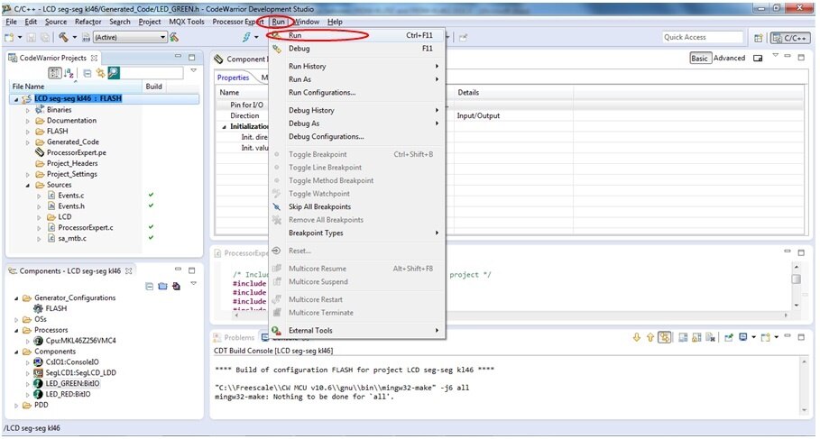
or alternately you can "Run" the project directly by following below steps:
Save all the files then clean and Build the project as shown below::
The build progress is shown below:

Now connect the board to USB through OpenSDA port of the board and Run the project as shown below:
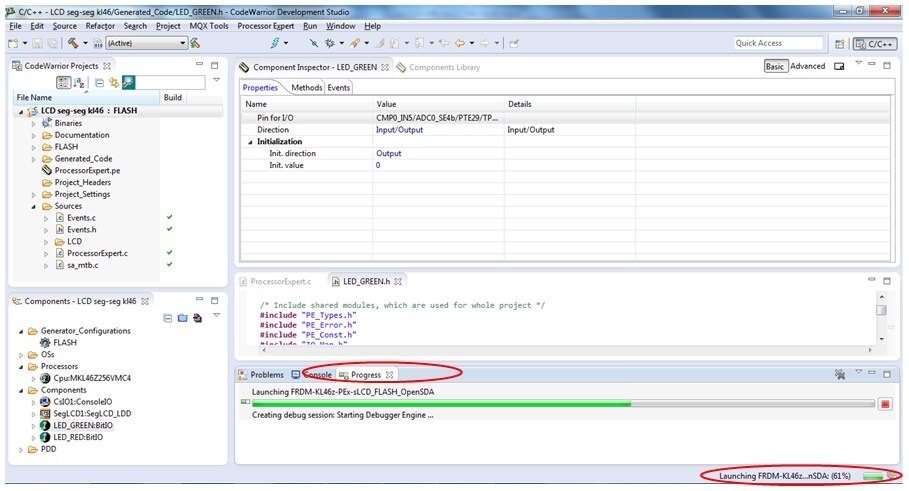
You can see Run progress bar as shown below:
After running the program you can see the project execution on the freedom board displaying all the segments one-by-one on the LCD.
The output snapshot is shown here:


A recording version of the board in action is available below
The project folder and LCD driver folder is enclosed here for quick reference.
Happy displaying LCD segments  . ...
. ...

