


This document / tutorial show the steps how to use the SDK2.0 with Kinetis Design Studio v3.0.0 implementation using FRDM-K64F freedom board.
Unlike previous SDK's, with the SDK v2.0 it only needs a generic 'new project wizard' inside KDS.
KSDK V2.0
Kinetis SDK v2 is a collection of comprehensive software enablement for NXP Kinetis Microcontrollers that includes system startup, peripheral drivers, USB and connectivity stacks, middleware, and real-time operating system (RTOS) kernels. The Kinetis SDK also includes getting started and API documentation along with usage examples and demo applications designed to simplify and accelerate application development on Kinetis MCUs.
The Kinetis SDK Builder allows you to get a customized SDK based on your specific evaluation platform or Kinetis MCU. Build your SDK now.
To quickly create new Kinetis SDK projects, or to clone existing projects, use the Kinetis SDK Project Generator.
All software is provided free-of-charge as assembly and C source code under permissive and open-source licensing. Support is provided through the Kinetis SDK Community Forum.
Below are the steps we are following for this tutorial:
01. Kinetis Design Studio (KDS):
We assume KDS3.2.0 has been installed in your computer or follow below steps to install it:
A new release of Kinetis Design Studio (KDS) is available: the version v3.2.0
The KDS v3.2.0 is an update with includes all existing updates to the v3.0.0 release. So instead downloading and installing v3.0.0 and then apply all updates, it is recommended that you use the v3.2.0 version instead. There is no need to uninstall an existing KDS v3.0.0: the new v3.2.0 is installed in a separate directory and can be used side-by-side with the previous version.
You can download latest version of KDS from Here or direct download from below link:
https://nxp.flexnetoperations.com/control/frse/download?element=7490587
02. Downloading a Kinetis SDK Package
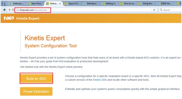
- Go to Welcome to Kinetis Expert | Kinetis Expert
- Login with your user NXP name/account and Click on 'Build an SDK' button as shown below
3.If this is your first configuration: select board/processor you want to use
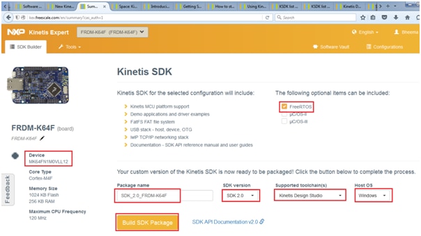
4. Customize the SDK version, toolchain and Host OS and Build the SDK as shown in above picture
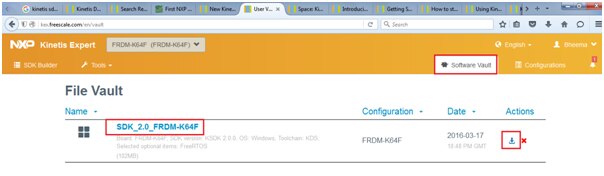
5. Check the Software vault and download the file as shown below
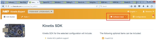
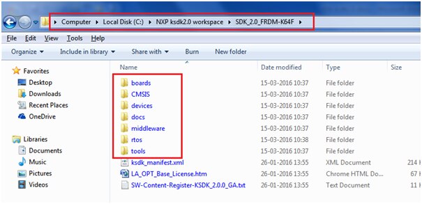
6.Unpack the downloaded archive file to a folder (recommended into c:\nxp (e.g. (c:\nxp\SDK_v2.0-K64F) or into /nxp on other systems)
In my case i have copied into below shown folder: “C:\NXP ksdk2.0 workspace\SDK_2.0_FRDM-K64F”
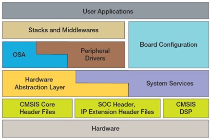
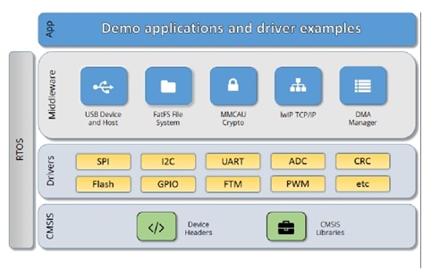
The Kinetis SDK architecture consists of five key components listed below.
- The ARM Cortex Microcontroller Software Interface Standard (CMSIS) CORE compliance device specific header files, SOC Header, and CMSIS math/DSP libraries.
- Peripheral Drivers
- Real-time Operating Systems (RTOS)
- Stacks and Middleware that integrate with the Kinetis SDK
- Demo Applications based on the Kinetis SDK
Installing Kinetis SDK v2.0 New Project Wizard in Kinetis Design Studio
First method:
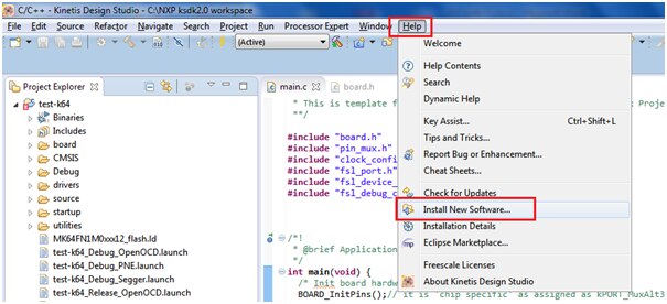
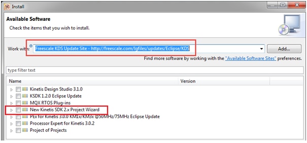
project wizard for Kinetis SDK v2.0 to be installed with the ‘Install New Software‘ menu in Eclipse:
Start Kinetis Design Studio
Select Menu Help > Install New Software
Select KDS Update site
(Freescale KDS Update Site - http://freescale.com/lgfiles/updates/Eclipse/KDS)
Install the New Kinetis SDK 2.x Project Wizard
Second method:
For offline installation: the wizard can be downloaded from the https://www.nxp.com/kds web site under the Kinetis Design Studio V3.0.0 downloads, e.g. for Windows it is here:
https://nxp.flexnetoperations.com/control/frse/download?agree=Accept&element=6321017
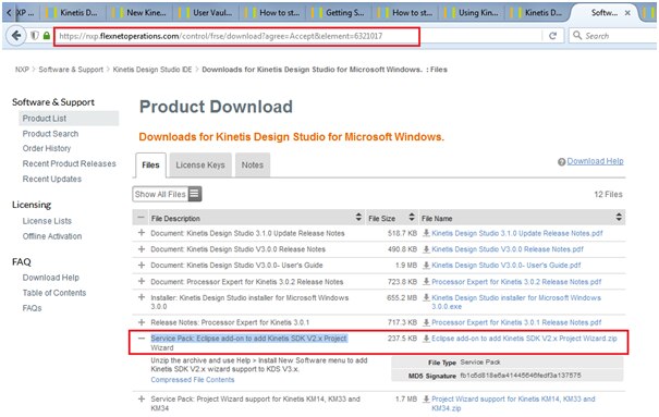
Download this file and Unzip the archive and use Help > Install New Software menu to add Kinetis SDK V2.x wizard support to KDS V3.x.
Click 'Add' button and type Name = "New Kinetis SDK 2.x Project Wizard", Location = select: NPWforKinetisSDK2x.zip
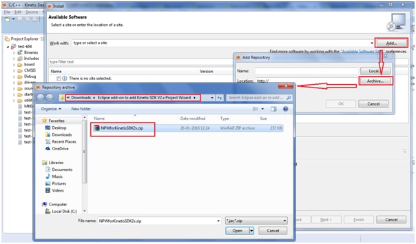
And Confirm installation to proceed to install the “NPWforKinetisSDK2x.zip”
‘New Project Wizard’ with SDK v2.0 and Kinetis Design Studio
With the example projects inside the SDK the Kinetis Design Studio is well supported. But what if I want to create a SDK project for my special board, or start with a ’empty’ SDK project?
Create new project
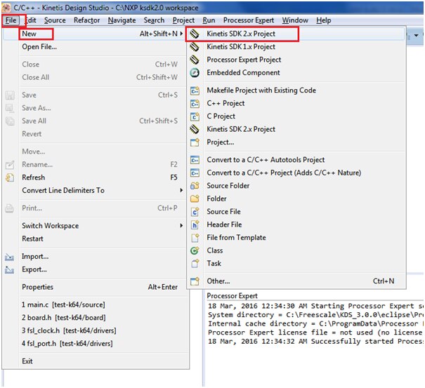
1. Start Kinetis Design Studio
2. Select the menu File > New > Kinetis SDK 2.x Project
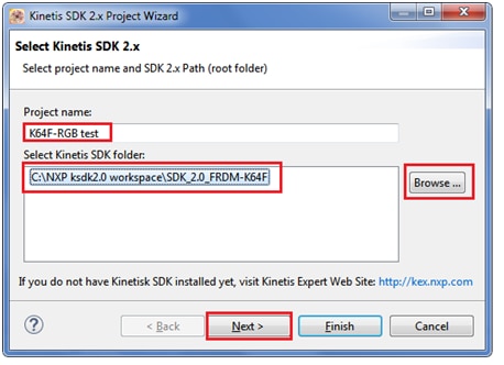
3. Enter project name of your choice i have named as “K64F-RGB test” and Browse to the location “C:\NXP ksdk2.0 workspace\SDK_2.0_FRDM-K64F “
Select where you have unzipped the SDK package from previous step and press Next
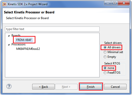
4. Select board or processor and press Finish as shown
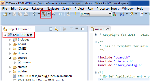
Your project is now created as shown below:


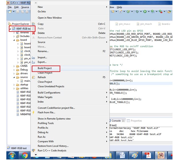
To check the project created is error free click on the hammer button to build the project as shown:
Now we will proceed to add our code to test RGB LED present on FRDM-K64F board:
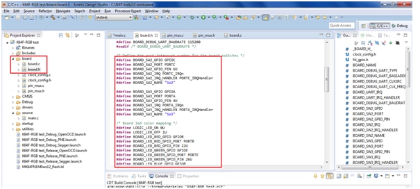
LED on board is connected to port pin as shown:
RED LED -> PORTB-22
Green LED -> PORTE-26
Blue LED -> PORTB-21
All the hardware configurations have been defined in file <board.h> inside the ‘board’ folder
We need to Enable the clock to the PORT module that the LED is on using CLOCK_EnableClock() function and Setup the red LED pin as GPIO -> PORT_SetPinMux() and initialise the RGB to on/off condition using LED_RED_INIT() function.
Below is the C code written:
#include"board.h"
#include "pin_mux.h"
#include "clock_config.h"
#include "fsl_port.h"
#include "fsl_device_registers.h"
#include "fsl_debug_console.h"

/*!
 * @brief Application entry point.
 */
int main(void) {
  /* Init board hardware. */
  BOARD_InitPins();
  BOARD_BootClockRUN();
  BOARD_InitDebugConsole();


  // Enable the clock to the PORT module that the LED is on.
        CLOCK_EnableClock(kCLOCK_PortB);
        CLOCK_EnableClock(kCLOCK_PortE);

        // Setup the red LED pin as GPIO
       PORT_SetPinMux(BOARD_LED_RED_GPIO_PORT, BOARD_LED_RED_GPIO_PIN, kPORT_MuxAsGpio);
 PORT_SetPinMux(BOARD_LED_GREEN_GPIO_PORT, BOARD_LED_GREEN_GPIO_PIN, kPORT_MuxAsGpio);
       PORT_SetPinMux(BOARD_LED_BLUE_GPIO_PORT, BOARD_LED_BLUE_GPIO_PIN, kPORT_MuxAsGpio);

       //initialise the RGB to on/off condition
       LED_RED_INIT(LOGIC_LED_OFF);
       LED_GREEN_INIT(LOGIC_LED_OFF);
       LED_BLUE_INIT(LOGIC_LED_OFF);


  /* Add your code here */

  for(;;) { /* Infinite loop to avoid leaving the main function */
    __asm("NOP"); /* something to use as a breakpoint stop while looping */

    for(int i=0;i<=10000000;i++);
       LED_RED_TOGGLE();

       for(int i=0;i<=10000000;i++);
          LED_GREEN_TOGGLE();

          for(int i=0;i<=10000000;i++);
             LED_BLUE_TOGGLE();
  }
}
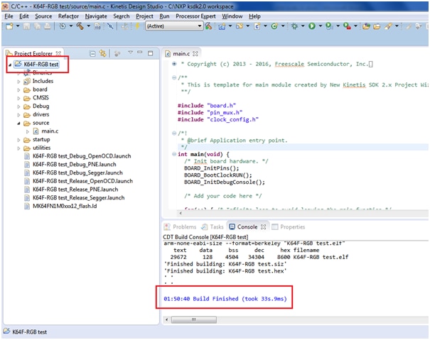
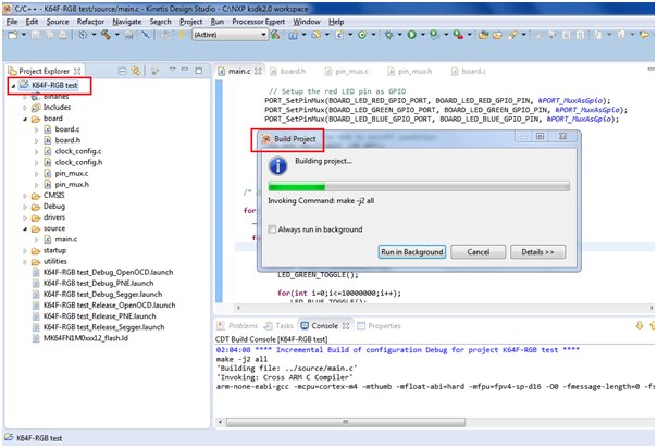
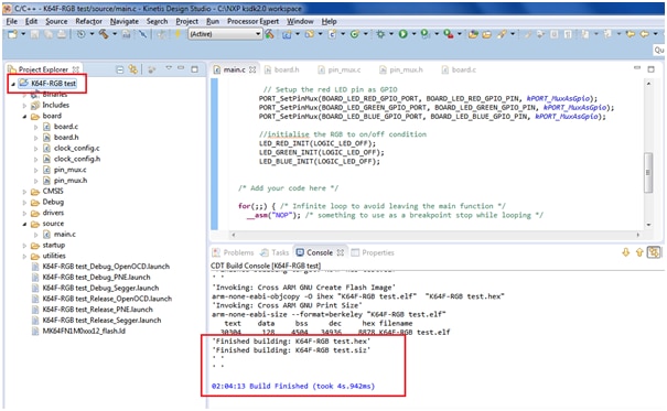
Now build the project to confirm it is working fine with no errors
You can see the project builds without errors
Now we will proceed to execute the project by debug process:
Make sure you have connected the K64F freedom board to USB port:
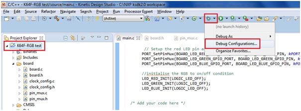
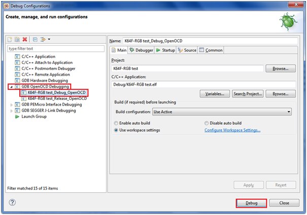
Open debug configuration as shown below and press ‘Debug’
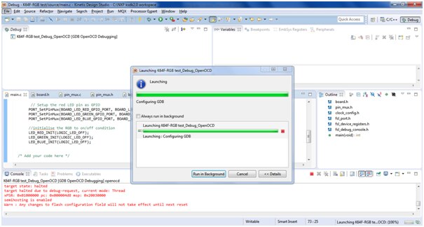
You will see below debug window:
Click on the resume button to ‘Run’ the project or ‘Step into’ and ‘Step over’ button for single stepping execution:
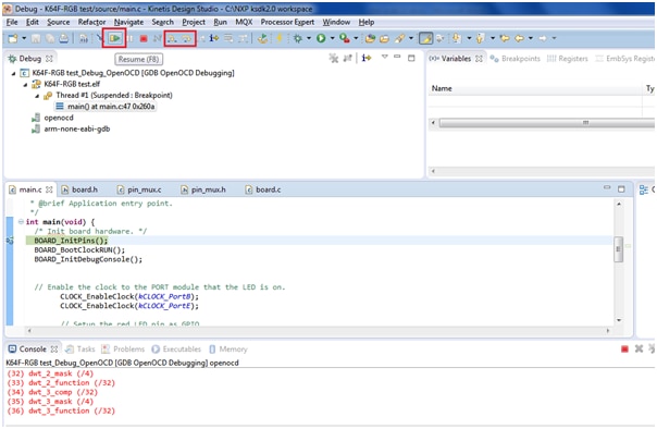
You can see RGB led glowing sequentially:
The project folder is attached along with this for quick evaluation
Happy Start with KSDK2.0... 


