


After doing some quick reading about this board I was quite interested to see how it pans out. Coming from an Arduino/AVR background anything that retails for under Au$15 with so much power is always going to be an interesting thing, and hopefully the FRDM-KL25Z lives up to the hype. First off, let's have a quick look at the hardware. For an inexpensive board it was packaged quite well:
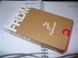
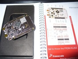
The contents however were quite minimal, the board itself and a quick sheet describing the board layout and a coupe of URLs to visit after the release date:
The board itself is quite small, and engineered t omatch closely to the size of an Arduino. Furthermore, the -LK25Z maintains hardware compatibility with Arduino-type shields:
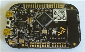
Note that the header sockets are not fitted, nor included with the board. Upon turning the board over one feature did make me smile - the addition of rubber feet:
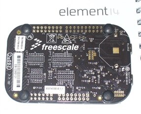
This is great as you don't risk shorting out the PCB on some random bits laying around the desk. The pinouts are also clearly labelled with the PCB silk screen. The blank space at the right-hand side is for an optional coin-cell holder when using the board for low-power applications.
I won't run through the hardware specifications, as Don Bertke has examined these in detail. What does interest me greatly is the user's out of box experience - the "OOBE". I spend a lot of time instructing new users - who will be attracted to this board becuase of the price. How easy is this to get going from opening the box to blinking an LED?
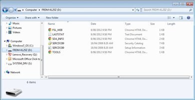
Due to this being a pre-release review, the public URLs on the packaging were not going where they needed to. Thankfully there is a quick-start .pdf with enough to get going. First you need to download and install the OpenSDA debug/programming interface drivers which are available here. Having to create an account to download this was a little tiresome, but such is life. Once installed, and restarting the computer you can connect the -KL25Z to the PC via your own USB cable and the SDA socket on the board. This allows the board to operate in MSD flash programming mode - where the board appears as another drive in Windows Explorer:
From this point you can simply drag and drop compiled project files (with .srec extensions) directly into the board at which point they will start running immediately. A few examples are provided, and the following video clip shows the LED blinking at a rate proportional to the value returned from the touch sensor:
Nothing too complex, but a nice test to see it all working. Now to find an IDE and install that. Our quick-start guide had links to two, IAR Embedded Workbench for ARM and KEIL MDK. After visiting their site and answering the survery questions, I downloaded the evaluation version of IAR Embedded Workbech for ARM. All 804 megabytes of it. The next morning after downloading the IDE installed without any surprises. Next you have to copy some installation files over to the board in bootloader mode, and finally patch up IAR. If you were to do this in one hit, allow about three hours or so depending on your download speed. You really need to follow the instructions in our quick-start guide to setup the IDE for the board, so be careful and take your time.
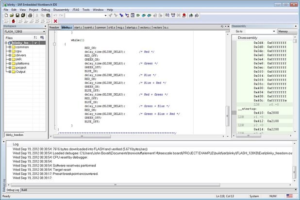
Finally it was time to open IAR and the blinky code. The quick-start guide will get you through to debugging and running - phew! We have blinking. At this point I'll check out and get back to work, returning with another example.
