


This is a project for interfacing FRDM-STBC-AGM01 sensor module to FRDM-KL46Z using Kinetis Design Studio 3.0 Kinetis SDK 1.2 Processor-Expert. This board is 9-axis Sensor Toolbox Development Board Enabled for sensor fusion with FXAS21002C 3-axis gyroscope and FXOS8700C 6-axis integrated e-compass, as part of the Freescale Freedom development platform.
This project has 4 state machines:
1) Default mode: this will prompt the user to press the push button
2) Accelerometer mode: when button is pressed once from its earlier state, it enters into accelerometer mode of working where the sensor FXOS8700CQ is active and displays 3 axis 14-bit accelerometer value.
3) Magnetometer mode: when button is pressed from its earlier state, it enters into this mode where the sensor FXOS8700CQ starts to work and 16-bit 3-axis magnetometer data is displayed on terminal.
4) Gyrometer mode: we need to press the push button as did earlier to enter into this mode. In this mode the sensor FXAS21002C is active and it displays 3-axis 16-bit gyro data on the terminal.
5) Temperature mode: You need to press the push button inorder to enter into this mode. In this mode the sensor device FXAS21002C is active and it displays temperature in degree Celsius.
The state machine diagram is as shown:

Hardware details of STBC-AGM01 9-axis Sensor
It has FXAS21002C 3-axis gyroscope and FXOS8700C 6-axis integrated e-compass as part of the
Freescale Freedom development platform
Schematic can be referred HERE

We are connecting I2CSDA0 of STBC to I2C1SDA of KL46Z freedom board and
I2CSCL0 of STBC to I2C1SCL of KL46Z which are PTE0 (SDA) and PTE1 (SCL) pins of KL46Z board.
The corresponding 7-bit I2C slave address of STBC sensor board are
FXAS21002C is 0x20
FXOS8700CQ is 0x1E
The interrupt pins of the sensor are connected as follows:
INT1- 8700 > J1-6 > PTD3
INT1-21002 > J1-12 > PTA5
The project implementation is as follows:

This project has the below components:
Fsl_i2c: I2CCom1
This component is configured with sensor interface with two devices FXOS8700CQ and FXAS21002C as shown below:

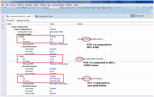
Fsl_gpio component
In the "Component Inspector" tab configure the GPIO component. The INT1_8700 output is connected to the PTD3 pin and the INT1_21002 pin to the PTA5 pin of the KL46Z MCU.
These both interrupt pins are configured as push-pull active-low outputs, so the corresponding PTD3/PTA5 pin configuration is GPIO with an interrupt on falling edge.
Fsl_debug_console
We are connecting the debug console to UART pins of KL46Z mcu to display the sensor output it is connected as shown
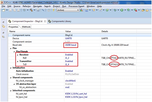
it is connected to PTA-1 > RxD and PTA-2 > TxD with baud rate of 19200
Wait

Connect the sensor board to FRDM-KL46Z board as shown below:

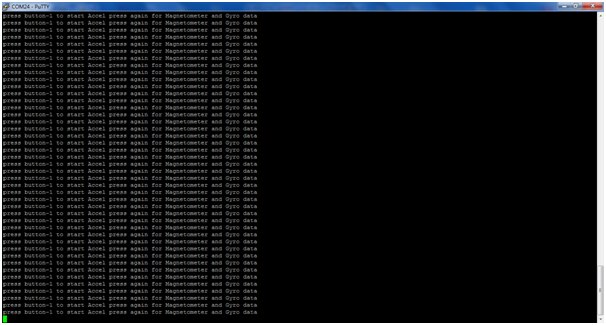
After compiling and executing the code you can see the output in an hyper terminal with baud rate of 19200 as shown below:

Mode-1 output window:
Mode-2 output (Accelerometer data):

Mode-3 output (Magnetometer data):

Mode-4 output (Gyro data):

Mode-5 output (Temperature data):

The video output is as shown below:
The executable are attached along with this to test at your end and the project folder for quick reference:
Happy interfacing with freescale 9-axis sensor board 

