


Here is a Project created using new KDS version 3.0 and Kinetis software development kit 1.2 on processor expert platform. This is a project for dimming an RED LED using TPM module (i.e varying the duty cycle of the PWM pulse) implemented on freedom board FRDM-KL43Z .
Requirements
To run successfully this exercise, you need first to download following packages (link enclosed):
- IDE toolchain Kinetis Design Studio (KDS) min v3.0
- microcontroller Library Kinetis Software Development Kit (KSDK) min 1.2
- FRDM-KL43Z materials (schematics, Quick Start Package and Sample Code Package)
- latest P&E Micro windows drivers and SDA Applications
Before connecting your FRDM-KL43Z for the first time to the USB port of your computer, install the P&E Micro windows driver to ensure a correct detection of the board.
Install first the IDE toolchain KDS and when the installation ended successfully, install the MCU Library KSDK keeping the proposed installation path c:\freescale\kds or ksdk unchanged.
Launch KDS and define your workspace path, then select Help, Install New Software, Add, Archive, C:\Freescale\KSDK_1.2.0\tools\eclipse_update, select KSDK_1.2.0_Eclipse_Update.zip and press Open, OK, select KSDK Eclipse Update, press Next, Accept the Licence Agreement and press Finish. The KSDK libraries are now directly available in the IDE toolchain.
The automated code generator Processor Expert is already included in the IDE Toolchain (available separately as Processor Expert Driver Suite for other IDE toolchains).
Tutorial instructions
The tutorial shows how to toggle LED with KSDK 1.2.0 in KDS 3.0 and Processor Expert using a Timer Output for FRDM-KL43Z.
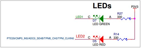
Guide is prepared for red LED which is connected to Timer/PWM Module 0 (TPM0), channel 2 (according to FRDM-KL43Z schematics).
Create new project
Create new project in KDS 3.0 with KSDK 1.2.0
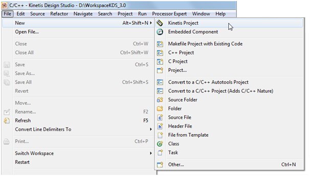
Type the project name e.g. “FRDM-KL43 Dimming using TPM” choose the board FRDM-KL43Z, mark off options Kinetis SDK and Processor Expert


Now, your project structure looks like this in the project explorer and Processor Expert windows:

Set Processor Expert Settings
Now, go to Components Library, find fsl_tpm component using filters KSDK 1.2.0 and Applicable to Project and by double click add the component to the Processor Expert Component View of your project.

Double click on tpmTmr1:fsl_tpm in Components View and Component Inspector view should open automatically
First turn the Component Inspector view to Classical view by unselecting the Tab View option.
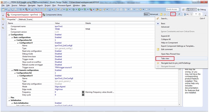
Enable to reload the counter on Trigger
Set the counter frequency to 1Hz with a Duty cyle of 50%
Allocate TPM0 Channel 4 to Pin LED2_RED (defined by board selection)
Select Clock source MCGIRCLK and choose the Prescaler Divide by 128
Enable the Initialization of TPM0 Channel 4


Save the configuration by pressing ctrl+s
Generate the Processor Expert Code for the component tpmTmr1 that we have just configured

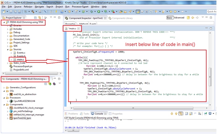
Insert the Code:
Now its time to insert the code for dimming the led i.e varying the duty cycle from 0 to 100% and again from 100% to 0%. The PWM slowly rises from from 0 and and intensity of the led slowly increases to its max 100% then again intensity decreases from 100 to 0%.
tpmTmr1_ChnConfig0.uFrequencyHZ = 1000;

while(1){
 TPM_DRV_PwmStop(FSL_TPMTMR1,&tpmTmr1_ChnConfig0, 4U);
//4 here represent channel no 4 connected to red led
            for(int i=100;i>=1;i--){
          tpmTmr1_ChnConfig0.uDutyCyclePercent = i;
 TPM_DRV_PwmStart(FSL_TPMTMR1,&tpmTmr1_ChnConfig0, 4U);
          for(int x=0;x<=300000;x++){} //delay in between for the brightness
 }      // end of for

 TPM_DRV_PwmStop(FSL_TPMTMR1,&tpmTmr1_ChnConfig0, 4U);
             for(int i= 0;i<=100;i++){
             tpmTmr1_ChnConfig0.uDutyCyclePercent = i;
 TPM_DRV_PwmStart(FSL_TPMTMR1,&tpmTmr1_ChnConfig0, 4U);
             for(int x=0;x<=300000;x++){} // delay in between for the brightness
    }      // end of for
 } // end of while
Explanation of coding:
tpmTmr1_ChnConfig0.uFrequencyHZ = 1000;
This line will change the pulse frequency to 1000 Hz
TPM_DRV_PwmStop(FSL_TPMTMR1,&tpmTmr1_ChnConfig0, 4U);
This will stop the pwm
for(int i=100;i>=1;i--){
tpmTmr1_ChnConfig0.uDutyCyclePercent = i;
TPM_DRV_PwmStart(FSL_TPMTMR1,&tpmTmr1_ChnConfig0, 4U);
for(int x=0;x<=300000;x++){} //delay in between for the brightness
} // end of for
The above lines will feed the variable value of ‘i’ from 100 to 1 dutycycle value to the channel configuration 0 which we have done it in processor expert window. After feeding the duty cycle value to channel configuration we start the pwm and insert some delay between brightness
Build your project by clicking on the hammer button as shown below:

Debugging the FRDM-KL43Z board for the first time, you need to define a Debug Configuration by selecting the appropriate option from the toolbar
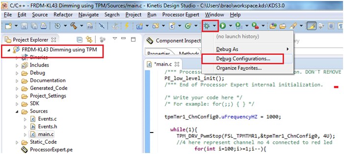
The FRDM-KL43Z embeds a multimode programming and debug interface easily reconfigurable by drag’n droping from the file explorer new SDA applications in Bootloader mode.
For this example, we are going to select the PEMicro OpenSDA Debug mode.
Select the Debugger tab to choose the Interface OpenSDA Embedded Debug - USB Port
You can now start the Debug session!!

Launch the configuration
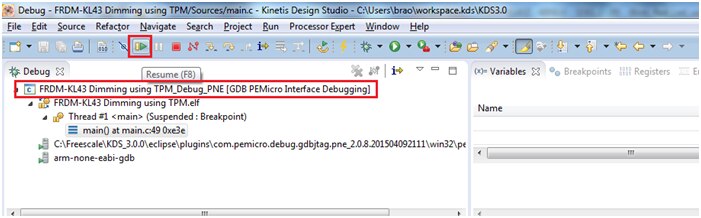
You should now see the Dimming of Red LED i.e brightness varies from 0 to 100%
Below is the video output
I have enclosed the project folder and executables for quick reference
