


Here is a Project created using new KDS version 3.0 and Kinetis software development kit 1.2 on processor expert platform. This project controls the brightness of LED i.e varying the duty cycle using two user push button, one button to increase the brightness and other to decrease the brightness of the LED connected through PWM of the KL43Z freedom board.
Requirements
To run successfully this exercise, you need first to download following packages (link enclosed):
- IDE toolchain Kinetis Design Studio (KDS) min v3.0
- microcontroller Library Kinetis Software Development Kit (KSDK) min 1.2
- FRDM-KL43Z materials (schematics, Quick Start Package and Sample Code Package)
- latest P&E Micro windows drivers and SDA Applications
Before connecting your FRDM-KL43Z for the first time to the USB port of your computer, install the P&E Micro windows driver to ensure a correct detection of the board.
Install first the IDE toolchain KDS and when the installation ended successfully, install the MCU Library KSDK keeping the proposed installation path c:\freescale\kds or ksdk unchanged.
Launch KDS and define your workspace path, then select Help, Install New Software, Add, Archive, C:\Freescale\KSDK_1.2.0\tools\eclipse_update, select KSDK_1.2.0_Eclipse_Update.zip and press Open, OK, select KSDK Eclipse Update, press Next, Accept the Licence Agreement and press Finish. The KSDK libraries are now directly available in the IDE toolchain.
The automated code generator Processor Expert is already included in the IDE Toolchain (available separately as Processor Expert Driver Suite for other IDE toolchains).
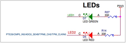
The Hardware connections of the KL43Z from schematic are:
GPIO pin connection of the board:
LED1 is connected to PTD-5 Green LED
LED2 is connected to PTE31 RED LED
And UART connections are:

Push button schematic connection are:

Button-1: PTC-3
Button-2: PTA-4
Simple Instruction to execute the project
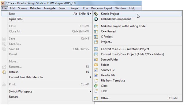
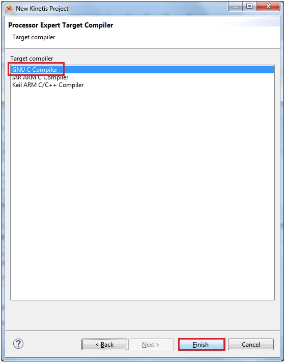
Step-1: Create a bare bone project
Step-2: Add the component debug_console, fsl_tpm, fsl_gpio to project
Step-3: Configure the hardware settings for UART and TPM user buttons
Step-4: Add the software code and compile/Build the project
Step-5: Execute the project and see the result.
Step-1: Create a bare bone project
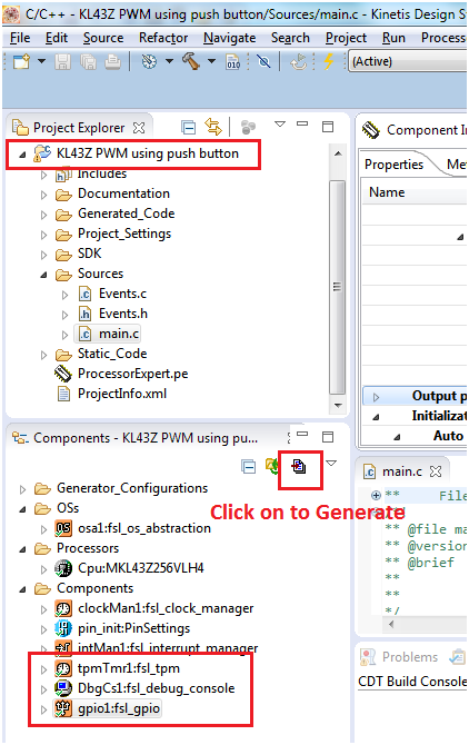
I have created a project by name “KL43Z PWM using push button” using same steps as earlier


Now the project looks like as shown below

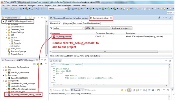
Step-2: Add the component debug_console, fsl_tpm, fsl_gpio to project
Now i am going to add the component fsl_debug_console and fsl_tpm from component library

Adding fsl_debug_console
Adding fsl_gpio component

Step-3: Configure the hardware settings for UART, TPM and GPIO components
Double click on the selected debug component “fsl_debug_console “ and select the baud rate of 19200 as shown below:

Now select the uart pins for these settings:

Settings for fsl_tpm
Double click on fsl_tpm component and make the below settings:
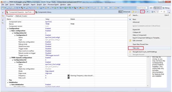
Enable to reload the counter on Trigger
Set the counter frequency to 1Hz with a Duty cyle of 50%
Allocate TPM0 Channel 5 to Pin LED2_Green (defined by board selection)
Select Clock source MCGIRCLK and choose the Prescaler Divide by 128
Enable the Initialization of TPM0 Channel 5


Save the configuration by pressing ctrl+s
Settings for fsl_gpio for connecting user push buttons
Double click on fsl_gpio component and make the below settings:


Now we need to enable the Interrupts for Port-A and Port-C in Events tab of the fsl_gpio component
Button-1: PTC-3, Button-2: PTA-4

Next we can see the interrupts will get enabled automatically in properties tab of the component as shown below:

Click on the generate button as shown below:
Step-4: Add the software code and compile/Build the project
Now write the below lines of codes inside the main file to control the PWM of Green LED through user push button.
First we need to write interrupt handler for Port-A and Port-C which is connected to user push buttons.
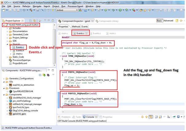
The code is given below:
/* For example: for(;;) { } */
int i=0;
extern unsigned char flag_up, flag_down;
 tpmTmr1_ChnConfig0.uFrequencyHZ = 1000;
 TPM_DRV_PwmStop(FSL_TPMTMR1,&tpmTmr1_ChnConfig0, 5U);
 tpmTmr1_ChnConfig0.uDutyCyclePercent = i;
 TPM_DRV_PwmStart(FSL_TPMTMR1,&tpmTmr1_ChnConfig0, 5U);
 debug_printf("LED  brightness %% value is %d \r\n",100-i);


while(1){
        if (flag_up == 1){
                flag_up = 0;
                i=i+5;
                    if(i<=100 && i>=0){
                    TPM_DRV_PwmStop(FSL_TPMTMR1,&tpmTmr1_ChnConfig0, 5U);
                    tpmTmr1_ChnConfig0.uDutyCyclePercent = i;
                    TPM_DRV_PwmStart(FSL_TPMTMR1,&tpmTmr1_ChnConfig0, 5U);
                    debug_printf("You have pressed button-down and brightness %% value is %d \r\n",100-i);
                    }

              if(i>100){
                    i=100;
                    debug_printf("You have pressed button-down and brightness %% value is %d Press the Down button to decrease brightness\r\n",100-i);
                      }


            }
        if (flag_down == 1){
                flag_down = 0;
                i=i-5;

                if(i<=100 && i>=0){
                    TPM_DRV_PwmStop(FSL_TPMTMR1,&tpmTmr1_ChnConfig0, 5U);
                    tpmTmr1_ChnConfig0.uDutyCyclePercent = i;
                    TPM_DRV_PwmStart(FSL_TPMTMR1,&tpmTmr1_ChnConfig0, 5U);
                    debug_printf("You have pressed button-down and brightness %% value is %d \r\n",100-i);
                    }
                    if(i<=0){
                          i=0;
                          debug_printf("You have pressed button-down and brightness %% value is %d Press the UP button to increase brightness \r\n",100-i);
                          }
                }
 } //while(1)

/*** Don't write any code pass this line, or it will be deleted during code generation. ***/
This code will write the PWM value to the TPM module connected to RED LED. The brightness of LED (varying the duty cycle) is increased/decreased using two user push button, one button to increase the brightness and other to decrease the brightness of the LED connected. And the result can be seen on board with response on hyper terminal.
Now compile/build the project by clicking the generate button as shown below:

The project compiles with with no error, we will proceed further in execution the project:

Step-5: Execute the project and see the result

Click on debug configuration and select the proper OpenSDA usb port from debugger tab as shown below:
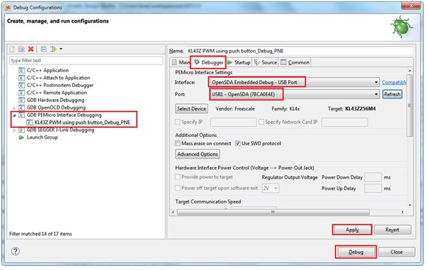

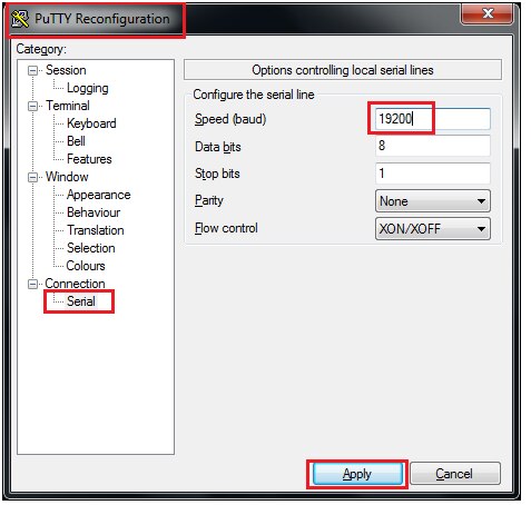
Before clicking on the resume button make sure to open the hyper terminal of your choice with baud rate of 19200, 8N1
I have opened putty with the said settings:
Now click on the resume button as shown below:

Working logic of the project:
The PWM will be varied for every 5%. i.e PWM increases from 0 to 100% for every 5% increase by pressing the button-1 and reaches to 100% (as led is connected in active-low led fades down from 100% to 0%) then reaches to 100% (led is switched off).
Again by pressing the button-2 from keyboard the PWM varies from 100% tp 0% duty cycle (brightness of the RED LED slowly increases from 0 to 100% as led is connected in active-low connection).
Below is my video output seen on the hyper terminal window:
I have enclosed the project folder and executables for quick evaluation
Happy working on PWM using push button 

