


Here is a Project created using new KDS version 3.0 and Kinetis software development kit 1.2 on processor expert platform. This project Toggles the RED and Green LED by pressing the push buttons SW-1 and SW-2 implemented using Interrupt function on KL43Z freedom board.
Requirements
To run successfully this exercise, you need first to download following packages (link enclosed):
- IDE toolchain Kinetis Design Studio (KDS) min v3.0
- microcontroller Library Kinetis Software Development Kit (KSDK) min 1.2
- FRDM-KL43Z materials (schematics, Quick Start Package and Sample Code Package)
- latest P&E Micro windows drivers and SDA Applications
Before connecting your FRDM-KL43Z for the first time to the USB port of your computer, install the P&E Micro windows driver to ensure a correct detection of the board.
Install first the IDE toolchain KDS and when the installation ended successfully, install the MCU Library KSDK keeping the proposed installation path c:\freescale\kds or ksdk unchanged.
Launch KDS and define your workspace path, then select Help, Install New Software, Add, Archive, C:\Freescale\KSDK_1.2.0\tools\eclipse_update, select KSDK_1.2.0_Eclipse_Update.zip and press Open, OK, select KSDK Eclipse Update, press Next, Accept the Licence Agreement and press Finish. The KSDK libraries are now directly available in the IDE toolchain.
The automated code generator Processor Expert is already included in the IDE Toolchain (available separately as Processor Expert Driver Suite for other IDE toolchains).
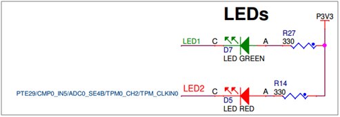
The Hardware connection of the KL43Z from schematic are:
GPIO pin connection of the board:
LED1 is connected to PTD-5 Green LED
LED2 is connected to PTE31 RED LED
And push button schematic is as shown below:
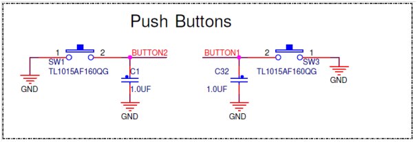
You can observe that there is no Pull-up provided on the hardware for the GPIO connected to push buttons. We have to add a pull up to our requirement, this can be done while creating project in KDS tool in fsl_gpio component.
Simple Instruction to execute the project
Step-1: Create a bare bone project
Step-2: Add the component fsl_gpio to project
Step-3: Configure the hardware settings for GPIO i.e push button and LED inside the fsl_gpio component
Step-4: Add the software code and compile/Build the project
Step-5: Execute the project and see the result.
Step-1: Create a bare bone project
I have created a project by name “KL43Z GPIO Interrupt Toggle” using same steps as earlier


Now the project looks like as shown below

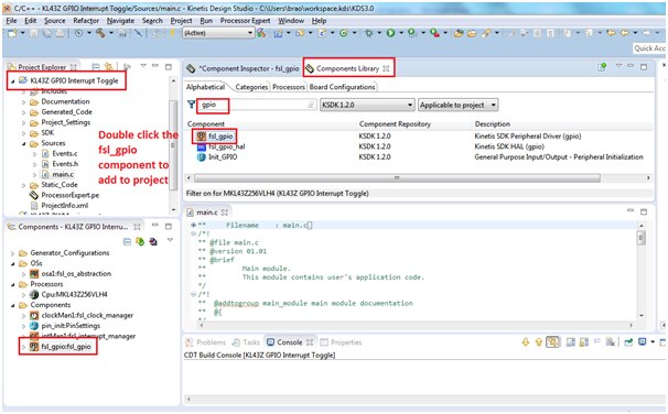
Step-2: Add the component fsl_gpio to the project
Now i am going to add the component fsl_gpio from component library
Step-3: Configure the hardware settings for LED and Push Button in fsl_gpio components
Double click on the selected component “fsl_gpio“ and make the settings for input and output side:
Below is settings for input configuration

Now select the input buttons from the dropdown list and select SW1 and SW2 as shown below:

As mentioned earlier from schematic there is no pullup conected to buttons hence we need to select the check box pull enable and pull select as shown in snap shot

As we need to enable interrupt click below opions
Button-1 is connected to PortA-4 and button-2 is connected to PortC-3

Select PORTA and PORTC to generate code

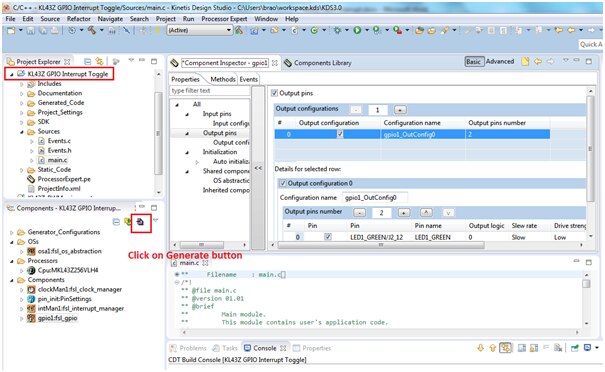
OUTPUT configuration:
Now we need to configure the output LED pins:

Green LED is connected to PTD-5 and RED LED is connected to PTE-31 as shown in schematic
Click on the generate button as shown below:
Step-4: Add the software code and compile/Build the project
After generating the code you can see the interrupt routines skeleton structure wil be generated inside “Events.c” as shown below:

We need to add our toggling the led function inside these routines:
Drag the GPIO_DRV_TogglePinOutput() from components to PORTA interrupt routine handler as shown below:
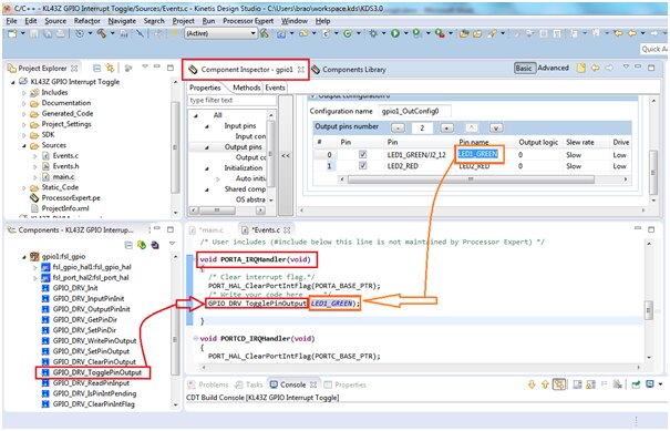
Similarly add the function for PORTC interrupt handler as shown below:

We have connected PORT-A to Green led which in turn connected to button-1 SW1 and PORT-C is connected to Red LED in turn connected to SW-2 push button
And inside main() just put infinite loop while ()

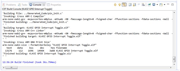
Now compile/build the project by clicking the hammer button as shown below:

The project compiles with with no error, we will proceed further in execution the project:

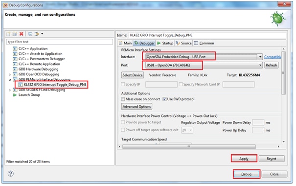
Step-5: Execute the project and see the result

Click on debug configuration and select the proper OpenSDA usb port from debugger tab as shown below:

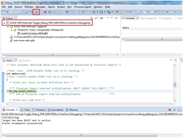
Below is my video output seen :
I have enclosed the project folder and executable for quick evaluation
Happy working with GPIO toggling using Interrupt