


Here is a Project created using new KDS version 3.0 and Kinetis software development kit 1.2 on processor expert platform. This is a project for Toggle a Green LED using PIT module of PE implemented using freedom board FRDM-KL46Z.
Requirements
To run successfully this exercise, you need first to download following packages (link enclosed):
- IDE toolchain Kinetis Design Studio (KDS) min v3.0
- microcontroller Library Kinetis Software Development Kit (KSDK) min 1.2
- FRDM-KL46Z materials (schematics, Quick Start Package and Sample Code Package)
- latest P&E Micro windows drivers and SDA Applications
Before connecting your FRDM-KL46Z for the first time to the USB port of your computer, install the P&E Micro windows driver to ensure a correct detection of the board.
Install first the IDE toolchain KDS and when the installation ended successfully, install the MCU Library KSDK keeping the proposed installation path c:\freescale\kds or ksdk unchanged.
Launch KDS and define your workspace path, then select Help, Install New Software, Add, Archive, C:\Freescale\KSDK_1.2.0\tools\eclipse_update, select KSDK_1.2.0_Eclipse_Update.zip and press Open, OK, select KSDK Eclipse Update, press Next, Accept the Licence Agreement and press Finish. The KSDK libraries are now directly available in the IDE toolchain.
The automated code generator Processor Expert is already included in the IDE Toolchain (available separately as Processor Expert Driver Suite for other IDE toolchains).
Tutorial instructions
The tutorial shows how to toggle LED with KSDK 1.2.0 in KDS 3.0 and Processor Expert using a PIT (Periodic Interrupt Timer) module Output for FRDM-KL46Z.
Guide is prepared to toggle Green LED which is connected to PTD5 (according to FRDM-KL46Z schematics shown below).
“PTD5/LCD_P45/ADC0_SE6B/SPI1_SCK/UART2_TX/TPM0_CH5”
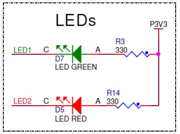
Green led connected to : PTD5
RED LED connected to : PTE29
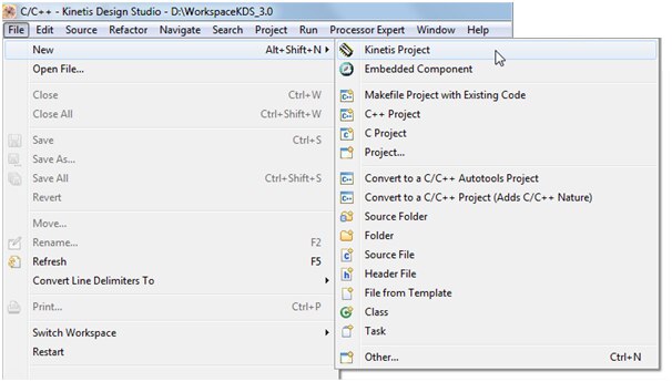
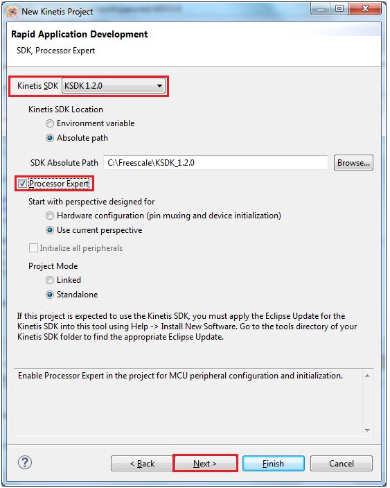
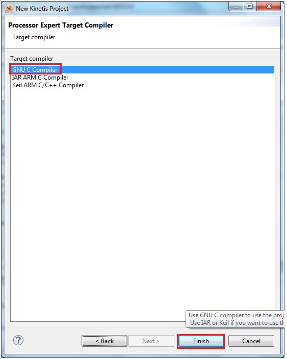
Create new project
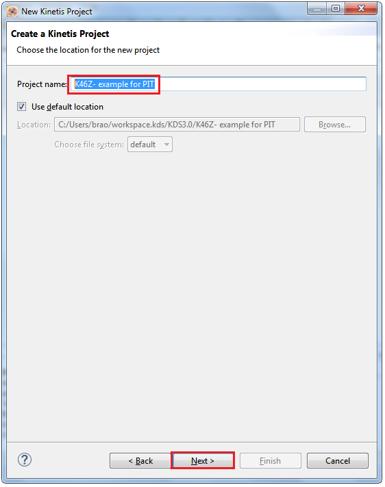
Create new project in KDS 3.0 with KSDK 1.2.0
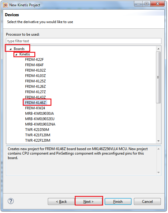
Type the project name” K46Z- example for PIT”, choose the board FRDM-KL46Z, mark off options Kinetis SDK and Processor Expert
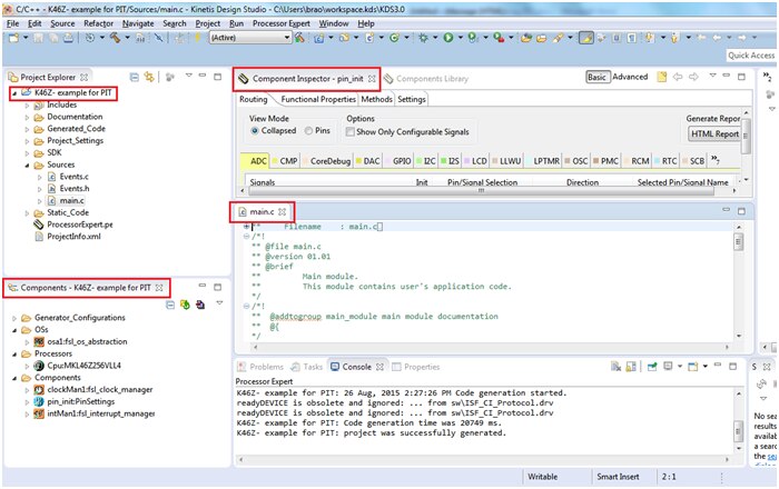
Now, your project structure looks like this in the project explorer and Processor Expert windows:
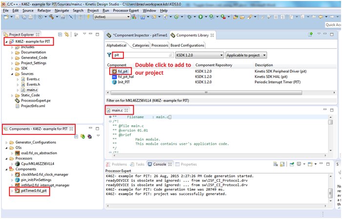
Add user components “fsl_pit”
Now, go to Components Library, find fsl_pit component using filters KSDK 1.2.0 and Applicable to Project and by double click add the component to the Processor Expert Component View of your project.
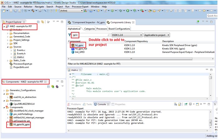
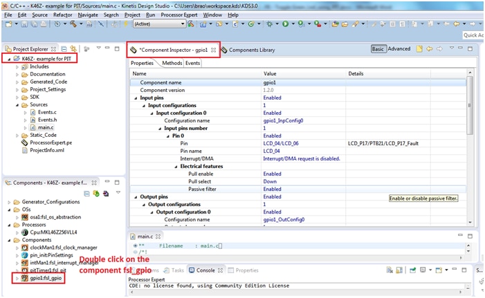
Adding fsl_gpio to our project:
Similarly search for gpio and double click on fsl_gpio component which is required for toggling LED as shown below:
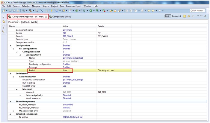
Double click on fsl_pit module from components windows and Component Inspector view should open automatically and uncheck the option for Tabs view which switches to classical view.
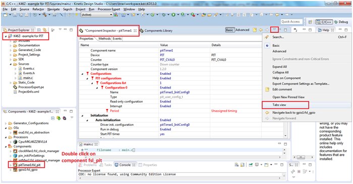
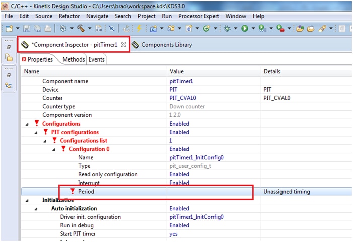
Configure the PIT module and click on “Period” option under configuration section as shown below:
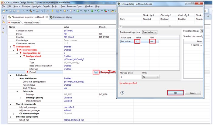
Change the value to 1 sec by clicking on  button ...
Now all the red markings will vanish which indicates it is error free
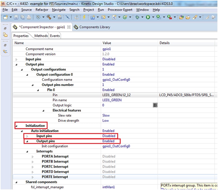
Now double click on the fsl_gpio module it looks like below:
Make the settings as shown below:
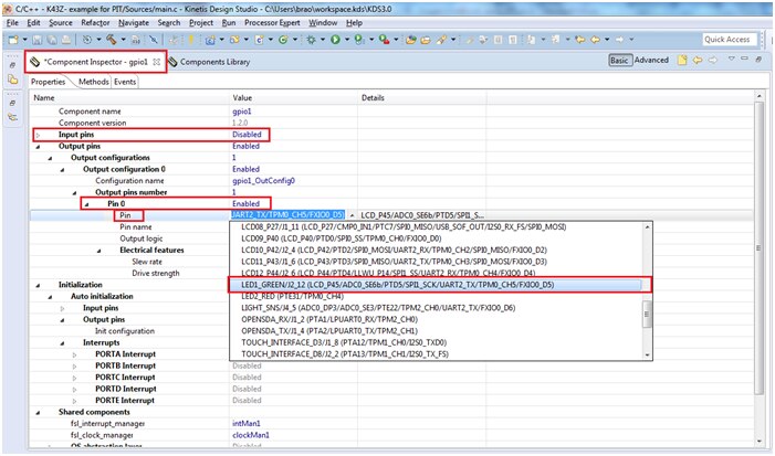
output pin 0 is configured to LED1_GREEN port pin PTD-5 which is connected to Green LED
and i.e disable the input pins as shown in below picture
Now all our modules are ready assigned, we need to generate code by pressing the generate icon as shown below:
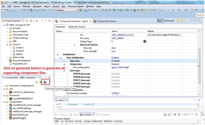
You can see all the required files will get generated under Generated_Code folder inside project folder.
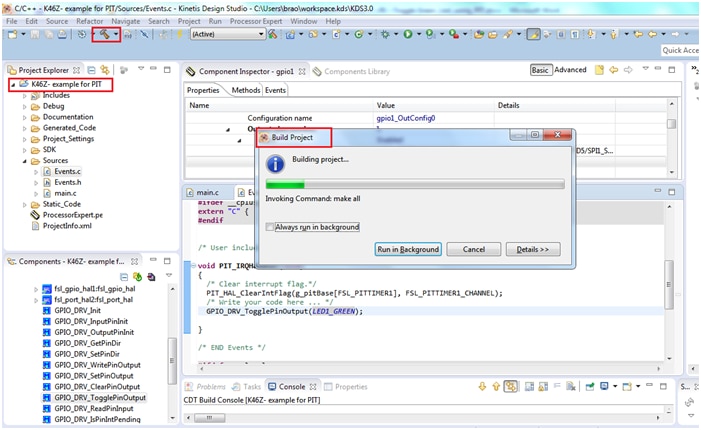
Now it’s time to include our task inside the PIT IRQ. The ISR can be found in Events.c file as shown below:
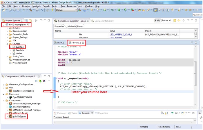
Now we are inserting the toggling function inside PIT0_IRQHandler()
The toggling function can be found from components window inside fsl_gpio module as shown below:
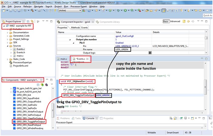
The function GPIO_DRV_TogglePinOutput(uint32_t pinName); accepts the parameter uint32_t pinName this can be found from the assigned name for blue led gpio we assigned in component inspector of fsl_gpio:
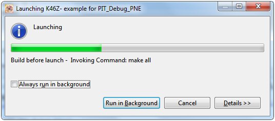
Now Build your project by choosing the right toolbar
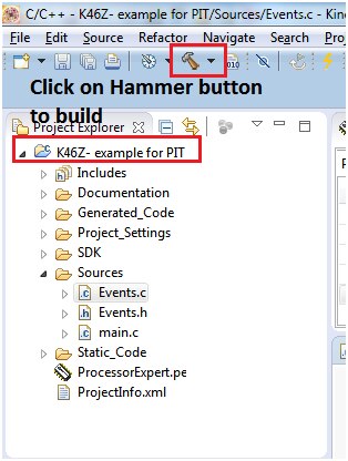
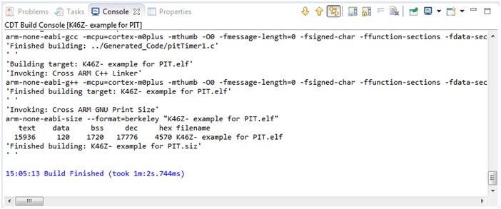
The project compiles with with no error, we will proceed further in execution the project:
Execute the project and see the result
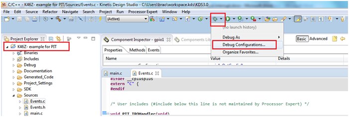
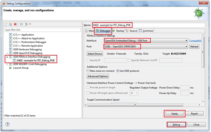
Click on debug configuration and select the proper OpenSDA usb port from debugger tab as shown below:
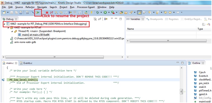
You should now able to see the Green LED blink with a 1Hz frequency i.e for every 1 sec of interrupt the LED toggles.
I have enclosed the project folder and binaries for quick reference and evaluation.