


This tutorial brings you on getting working with 4-digit (4X8) segment LCD present in KL43Z freedom board.
Installing the Kinetis SDK v1.3.0 / Eclipse Update
Download SDK1.3.0 from below link and install it. By default it gets installed in “C:\Freescale\KSDK_1.3.0” folder
Before using KDS IDE with KSDK, the KSDK Eclipse Update must be applied. Without this update, Eclipse cannot generate KSDK-compatible projects.
To install the update, follow these instructions:
Select "Help" -> "Install New Software"

In the Install New Software dialog box, click the "Add" button in the upper right corner. Then, in the Add Repository dialog, select the "Archive" button.
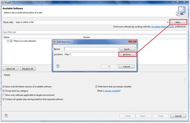
In the Repository archive dialog box, browse the KSDK install directory folder and select the KSDK_1.3.0_Eclipse_Update.zip file.

Click "Open", and the "OK" button in the Add Repository dialog box. Then The KSDK update shows up in the list of the original Install dialogs. Check the box to the left of the KSDK Eclipse update and click the "Next" button in the lower right corner.
Follow the remaining instructions to finish the installation of the update.
Build the platform library
The platform library is required to create a NEW project and does not build without it.
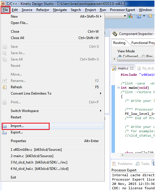
Select "File->Import" from the KDS IDE menu. In the window that appears, expand the "General" folder and select
"Existing Projects into Workspace". Then, click the "Next" button.

Click the "Browse" button next to the "Select root directory:" option. And choose the folder
“C:\Freescale\KSDK_1.3.0\lib\ksdk_platform_lib\kds\KL43Z4” as shown below

To Build the platform library click on hammer button as shown below:

The library starts building after clicking on the hammer button
The libraries file “libksdk_platform.a“ is generated.
LCD connection Details:
Segment LCD modules are simple and very low power LCD displays. They can have a large number of segments in the form of dots (pixels) or symbols (parts of 7 segment characters or special images) and a large number of pins to enable these segments to be controlled. SLCD controllers tend to have a high number of pins to handle large GLCD modules. These pins can be configured as back-plane or front-plane pins and generates the required multiplexing and waveforms needed to continuously refresh the SLCD.
Rather than have one connection for each segment, the segments are typically multiplexed so that less control lines are needed to control the same number of individual segments.
To illustrate this, the Lumex LCD-S401M16KR, as used on the Freescale FRDM-KL46Z is used as reference. The following is an excerpt from its data sheet showing its characteristics and how its 12 pins are connected to its elements:
Characteristics of Lumex LCD-S401M16KR are given below:

Connection details of Luminex LCD-S401M16KR

And the display’s elements are illustrated below according to their references in the Connection table in the original data sheet:

s401 segments layout
This display has 12 pins, which are all connected to a driving pin on the SLCD controller. There are 4 common pins and so the driving mode is ¼ duty cycle, since each of the common pins are driven for ¼ of the cycle period. Each of the common lines is connected to 8 LCD segments. Taking COM0 as an example the 8 segments that are controlled by it are show in the following diagram.

This means that when the COM0 line is being driven up to 8 segments can be turned on, depending on the state of the 8 segment pins. The 8 segment pins (5..12) thus control these 8 segments during this driving phase and can turn all on, all off, or an combination in between.
Since there are 4 phases (4 COM pins), each controlling 8 segments during that phase, a total of 32 segments can be controlled – this corresponds to the number of segments that the SLCD physically has. The other 3 COM drive combinations are not shown in a diagram here but can be easily read from the original data sheet table.
In order to configure the SLCD driver to match this display 4 of its LCD pins are configured as COM drive pins and 8 as segment drive pins. The COM drive pins are configured to drive in different phases (eg. COM0 in phase 1, COM1 in phase 2, COM2 in phase 3 and COM3 in phase 4, where each of the phases are repeated according to ¼ duty driving mode). The duty mode and any other specific configuration are also set in the SLCD controller.
s401 pin | Pin connection | KL43 LCD Pin |
1 | (COM0) | LCD_P59 |
2 | (COM1) | LCD_P60 |
3 | (COM2) | LCD_P14 |
4 | (COM3) | LCD_P15 |
5 | (1D/1E/1G/1F) | LCD_P20 |
6 | (DP1/1C/1B/1A) | LCD_P24 |
7 | (2D/2E/2G/2F) | LCD_P26 |
8 | (DP2/2C/2B/2A) | LCD_P27 |
9 | (3D/3E/3G/3F) | LCD_P40 |
10 | (DP3/3C/3B/3A) | LCD_P42 |
11 | (4D/4E/4G/4F) | LCD_P43 |
12 | (COL/4C/4B/4A) | LCD_P44 |
Tutorial instructions to demonstrate sLCD
Create new project in KDS 3.0 with KSDK 1.3.0

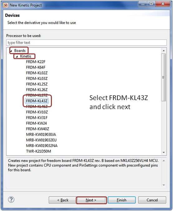
Type the project name “SLCD Test-KL43Z” choose the board FRDM-KL43Z, mark off options Kinetis SDK and Processor Expert as shown in below snaps


Now, your project structure looks like this in the project explorer and Processor Expert windows:

Set Processor Expert Settings
Now, go to Components Library, find fsl_slcd component using filters KSDK 1.3.0 and Applicable to Project and by double click add the component to the Processor Expert Component View of your project.

Now we need to configure the slcd pins according to the lcd connection as shown below:
s401 pin | Pin connection | KL43 LCD Pin |
1 | (COM0) | LCD_P59 |
2 | (COM1) | LCD_P60 |
3 | (COM2) | LCD_P14 |
4 | (COM3) | LCD_P15 |
5 | (1D/1E/1G/1F) | LCD_P20 |
6 | (DP1/1C/1B/1A) | LCD_P24 |
7 | (2D/2E/2G/2F) | LCD_P26 |
8 | (DP2/2C/2B/2A) | LCD_P27 |
9 | (3D/3E/3G/3F) | LCD_P40 |
10 | (DP3/3C/3B/3A) | LCD_P42 |
11 | (4D/4E/4G/4F) | LCD_P43 |
12 | (COL/4C/4B/4A) | LCD_P44 |
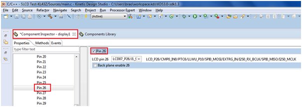
Configure pin-14 as backplane assigned to COM2 as shown below:

Similarly for pin-15 assigned to COM-3

Similarly for COM0 connected to pin-59

COM-1 connected to pin-60 as backplane

And for remaining segment connection for pins assigned to (not as Backplane)
Pin-20, pin-24, pin-26, pin-27, pin-40, pin-42, pin-43, pin-44


Next we need to change the duty cycle of the segment LCD to be ¼ as shown below:

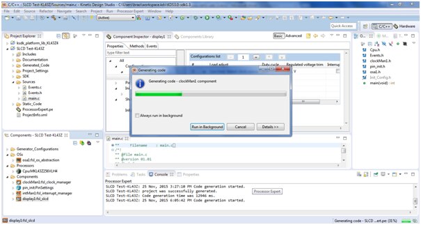
All the lcd configuration is now completed. We shall proceed to generate the corresponding code by clicking on the ‘generate code’ as shown below:

The tool generate code as shown below
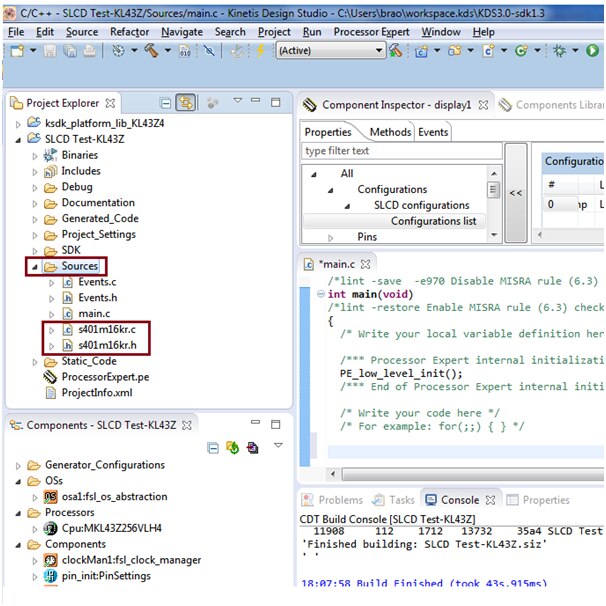
We need to add the driver header file for slcd “s401m16kr.c” and “s401m16kr.h” inside the source folder:
These files can be found from location where you have installed KSDK 1.3.0 version
“C:\Freescale\KSDK_1.3.0\examples\frdmkl43zkl33z4\demo_apps\slcd_low_power_demo”
To add these files follow below steps:


Select the file location as mentioned and select the two files “s401m16kr.c” and “s401m16kr.h” in the check box as shown:

Now you can see these files are added in your project source folder as shown
Insert the Code:
Now its time to add our code to execute and test each segments of LCD
char seg[]={20,24,26,27,40,42,43,44}; // seven segment connection
  char col[]={0,1,2,3}; //column of lcd

  int s,c,i;

  //initialize and configuring the slcd settings we did in PE
  SLCD_DRV_Init(display1_IDX, &display1_InitConfig0);
  SLCD_DRV_SetAllPinsConfig(display1_IDX, &display1_PinsCfg);

  // setting of Backplane connected to com0-com3
  SLCD_DRV_SetBackPlanePhase(display1_IDX, 59, kSLCDPhaseA);
  SLCD_DRV_SetBackPlanePhase(display1_IDX, 60, kSLCDPhaseB);
  SLCD_DRV_SetBackPlanePhase(display1_IDX, 14, kSLCDPhaseC);
  SLCD_DRV_SetBackPlanePhase(display1_IDX, 15, kSLCDPhaseD);

// starting the slcd function
  SLCD_DRV_Start(display1_IDX);


  for(;;){
// to glow all the segment in order
for(s=0;s<=7;s++){
                           for(c=0;c<=4;c++){
                                      SLCD_WritePin(seg[s],col[c],1 );
                                      for(i=0;i<=2000000;i++); // delay for user to see the segment glowing
                                    }
 }
// to erase all the segment
for(s=0;s<=7;s++){
                                     for(c=0;c<=4;c++){
                                                 SLCD_WritePin(seg[s],col[c],0 );
                                     }
 }
for(i=0;i<=5000000;i++);       // small delay
 }  //end of for(;;)
Add these lines of code inside main as shown below

Now compile and build the project by clicking the hammer button as shown below:

You can see the build result in console window as shown below:

Now we will execute our code by debug method:

Next select the PEMicro debugging interface and OpenSDA type as shown below:

After clicking on debug the system launches our project and below window appears.

You will see a Debug execution window, press Resume button as shown below:

You can see the segments of LCD glows one-by-one as shown in the output video:
I have enclosed the project folder and executable srec file for your reference:
Happy displaying slcd using KSDK1.3.0 ... 


