


This blog brings you a short out-of box demo Wireless Connectivity Example Demos on the FRDM-KW40ZFRDM-KW40Z for newly introduced freedom board FRDM-KW40ZFRDM-KW40Z which is a low-cost development platform enabled by the Kinetis W series KW40Z/30Z/20Z(KW40Z family built on the ARM Cortex-M0 processor The KW40Z is an ultra low-power highly-integrated single-chip device that enables Bluetooth Smart/Bluetooth Low Energy(BLE v4.1 and IEEE 802.15.4-2011 RF connectivity for portable extremely low-power embedded systems
The KW40Z processor family is based on an ARM M0+ core running at 48MHz. The processor integrates a buck-boost DC/DC converter, supporting a wide range of operating voltages from 0.9 V to 4.2V The KW40Z MCU integrates a 2.4 GHz transceiver supporting a range of FSK/GFSK and O-QPSK modulations, an ARM Cortex-M0+ CPU, 160 KB Flash and 20 KB SRAM, BLE Link Layer hardware, 802.15.4 packet processor, hardware security and peripherals optimized to meet the requirements of the target applications.
These processor family offers Dual mode Support which allows the system to concurrently participate in an 802.15.4 based network and BLE, eliminating the need for multiple radios, reducing system complexity and ultimately cost.
Take advantage of the robust enablement package that includes the BLE Host Stack, 802.15.4 MAC and Simple MAC (SMAC) software protocol stacks, RTOS, Kinetis Software Development Kit (KSDK) and development tools from IAR.
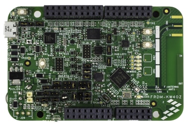
The FRDM-KW40ZFRDM-KW40Z kit contains two boards enabling point-to-point out of the box connectivity Each board can be configured as a Freedom development board or as a Freedom shield The FRDM-KW40ZFRDM-KW40Z hardware is form-factor compatible with the Arduino R3 pin layout providing a broad range of expansion board options
The FRDM-KW40ZFRDM-KW40Z features a highly-sensitive optimized 2.4 GHz radio with PCB F-antenna which can be bypassed for connection to test equipment via SMA connection multiple power supply options push and capacitive touch buttons switches LEDs and integrated sensors
Highlights:
· Multi-Protocol Radio – High performance radio supporting Bluetooth Smart/Bluetooth Low Energy (BLE) v4.1 and IEEE 802.15.4 based standards
· Low Power – Low transmit, receive and standby currents as low as 206nA that maximizes battery life including standard coin-cells
· Analog Integration – DC-DC Converter with Buck or Boost configuration, high-precision 16-bit Analog-to-Digital (ADC) converter for highly accurate sensor measurements, 12-bit Digital-to-Analog (DAC) and 6-bit Comparator (CMP)
· Software – Fully compliant, certified Bluetooth Low Energy and802.15.4 MAC

To proceed further the below are the prerequisites:
1) The freedom hardware board i.e FRDM-KW40ZFRDM-KW40Z-2 No’s as shipped in a box
(It is preloaded with“Wireless Connectivity Connectivity Test Application Example Demos on the FRDM-KW40ZFRDM-KW40Z
2) Installed “KW40Z_Connectivity_Software_1.0.0” software
3) IAR Embedded Workbench for ARM (EWARM) version 7.40.2 or later
[http://supp.iar.com/Download/SW/?item=EWARM-EVAL]
(Optional if you are running a pre-loaded example on KW40Z)
Download KW40Z Connectivity Software
The KW40Z Connectivity Software package integrates the Kinetis Software Development Kit v1.3 and all the wireless connectivity stacks required to develop your solution using IEEE 802.15.4 and/or Bluetooth Low Energy. Download the software Enablement package and tools required to build and run the connectivity solutions for KW40Z / KW30Z / KW20Z.
Install Your Toolchain
IAR Embedded Workbench for ARM (EWARM) version 7.40.2 or later is the development toolchain used to deploy software applications using the NXPivity stacks. NXP provides example EWARM workspace projects for you to start your development.
Note: Right now, the only supported tool chain is IAR Embedded Workbench for ARM, currently work is under progress on the enablement of NXP KDS for the Connectivity stacks.
Connectivity Test Application
The MKW40Z Connectivity Test Application is a SMAC based Demo Application which provides the user with means to test basic transmission-reception functionalities along with several advanced testing features based on the ASP and SMAC APIs.
The SMAC based“Connectivity Test demo application requires a serial terminal program to communicate with the FRDM-KW40ZFRDM-KW40Z board Any serial port terminal program is suitable but for the purposes of this demo Putty terminal is chosen..
Begin our Test:
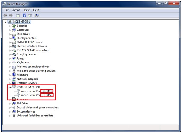
Plug in both the boards to your computer and open the device manager from your control panel, you can see there are two com ports connected as shown below (in my case it is com53 and com 54)
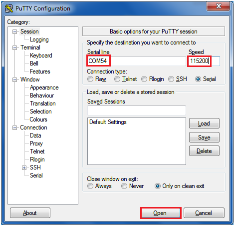
Open any hyper terminal application from your computer, in my computer i am having putty terminal
Configure to open COM54 port connected board:
Similarly open the COM53 port connected board from your putty terminal.
After both the board configured putty is opened reset the board once you can see welcome window as shown below:
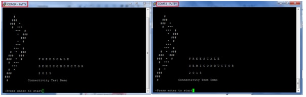
The application displays a logo screen and waits for user intervention. When the [ENTER] key is pressed, the application will show the main menu. If any other key is pressed, the logo screen is redisplayed with on-screen instructions.
After pressing enter button you can see SMAC Software Demo Application menu as shown below i.e Connectivity test interface main menu
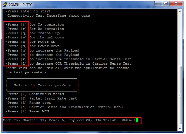
According to the above figure, the following keys have the effect described below:
• ‘t’ : brings up the configuration menu for the transmitter in both PER and Range tests.
• ‘r’ : brings up the configuration menu for the receiver in both PER and Range tests.
• ‘q’ : increments channel number. If pressed when current channel is 26, the channel number will change to 11.
• ‘w’ : decrements channel number. If pressed when current channel is 11, the channel number will change to 26.
• ‘a’ : increments output power value. If output power is at maximum and this key is pressed, the output power will go to minimum (in this case 0x03).
• ‘s’ : decrements output power value. If output power is at minimum and this key is pressed, the output power will go to maximum (in this case 0x0F). These are not directly mapped to dBm values. Instead the output power value is written to the appropriate register. The user should consult the reference manual to determine the relationship between selected value and power in dBm.
• ‘n’ : increments the length of the payload. This value is used in both PER TX test to build-up the payload and in Transmission Control test for the same reason.
• ‘m’ : decrements the length of the payload. Incrementation and decrementation is performed in the [17, 116] interval. All overflows at one end lead to setting the other end’s value.
• ‘k’ : increments the CCA threshold for the Carrier Sense test. In this test the CCA before TX algorithm is implemented at application level and the channel idle threshold is established using this parameter.
• ‘l’ : decrements the CCA threshold for the Carrier Sense test.
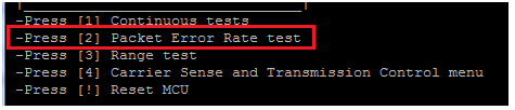
To start any test, you can follow the on-screen instructions. We are going with Packet Error Rate test
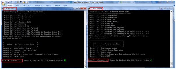
Both of the board comes in Tx mode by default as shown below:
In packet error rate we are transmitting XX numbers of packet from transmit window and checking the same number of packets are been received in receive window, and if there is error in receiving packets it will give the error rate.
For this we need to configure one of the board to be in RX mode for configuring press button ‘r’ on one of the terminal to change in rx mode as shown below:
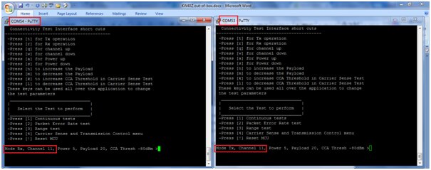
In my setup COM54 is configured as receiver terminal and COM53 as Transmit terminal as shown above
Now press ‘2’ on both terminals to run as “Packet Error Rate Test”
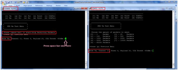
You can see different options on the RX board now press ‘space bar’ to start receiving packets i.e the terminal is in receiving mode and keep in listening for the packets on the channel
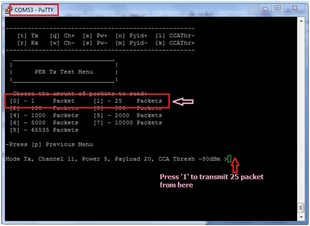
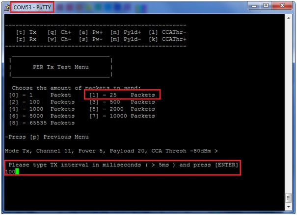
Press ‘1’ here in transmit terminal to send 25 packets it will ask TX interval in milliseconds i have given 100ms. Now press enter to send packets
Now you can see the sending packets from transmit window and same thing is received in receive window i.e in COM54 port terminal both happens simultaneously as shown below:
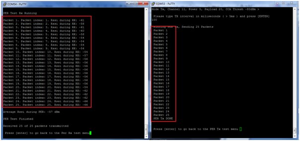
You can see the packet index along with RSSI during RX and average RSSI of the PER
The Video output execution is shown in below video:
Happy Executing out of box demo on FRDM-KW40Z (wireless MCU Cortex M0+)... 