


The LPCXpresso family of boards provides a powerful and flexible development system for NXP 's Cortex-M MCUs. The LPCXpresso4367 board has been developed by NXP to enable evaluation of and prototyping with the LPC4300 series of MCUs, and features the LPC4367 in its 100 PIN BGA package option.
LPCXpresso is a low-cost development platform available from NXP supporting NXP's ARM-based microcontrollers. The platform is comprised of a simplified Eclipse-based IDE and low-cost target boards which include an attached JTAG debugger. LPCXpresso is an end-to-end solution enabling embedded engineers to develop their applications from initial evaluation to final production.
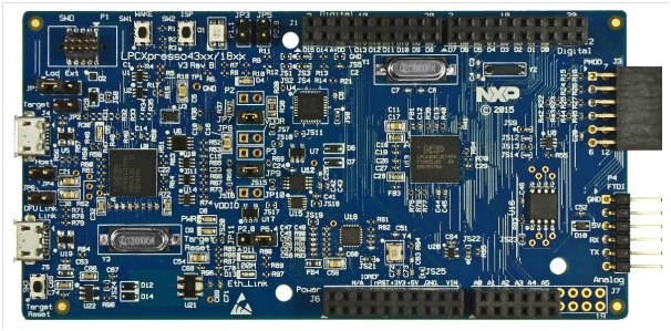
The LPCXpresso4367 board includes the following features:
1. LPC4367 dual-core (M4F and M0+) MCU running at up to 204 MHz
2. On-board high-speed USB based debug probe with CMSIS-DAP and LPCXpresso IDE Redlink protocol options, can debug the on-board LPC4367 or external target
3. Support for external debug probes
4. Tri-color LED
5. Target Reset, ISP and WAKE buttons
6. USB, UART and QSPI flash boot option configuration options
7. Expansion options based on Arduino UNO R3 and Pmod, plus additional expansion port pins
8. On-board 1.8/3.3 V or external power supply options
9. On-board Ethernet PHY (output available at expansion connectors)
10. High speed USB A/B connector for host or slave operation
11. 8 Mb Macronix quad SPI flash
12. UART, I²C and SPI port bridging from LPC4367 target to USB via the on-board debug probe
13. FTDI UART connector
14. Compatible with LPCXpresso4337 mbed SDK
By default, the LPCXpresso4367 is configured to use the on-board debug probe (Link2) to debug the on-board target (Target MCU). By default the Target MCU UART0 is connected to the FTDI header at P4. This can be used for sending debug messages out to a host computer via a suitable cable. The Target MCU UART0 can also be connected through a virtual communication port (VCOM) UART bridge Link2 function to a host computer connected to the USB Link2 (J5).
Pre-requisites:
1. Installed LPCXpresso IDE tool chain or you can download it from below link:
https://www.lpcware.com/lpcxpresso/download
2. LPCOpen examples and libraries for LPC4367 MCU
or
when LPCXpresso is installed the example and libraries can be found at below location
C:\nxp\LPCXpresso_8.1.4_606\lpcxpresso\Examples\LPCOpen
3. LPCXpresso LPC4367 development board hardware OM13088OM13088
Its NXP weblink and downloads can be found from below link:
Let us begin with our demonstration:
Now you have the source project which has been downloaded the LPCOpen examples and libraries for LPC4367 MCU from
or by default the source for LPC4367 will be available in below folder when LPCXpresso had installed in your machine:
“C:\nxp\LPCXpresso_8.1.4_606\lpcxpresso\Examples\LPCOpen”

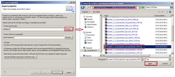
Start the LPCXpresso IDE and import the LPCOpen zip file by clicking Import project(s) in the “Start here panel.”
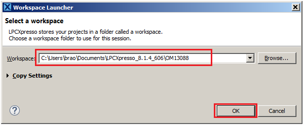
Open LPCXpress and select the workspace of your own as shown below:
Click on import project from quick start menu

Click on next

Now select the chip library and chip library for LPC4367 device and the example to be executed, in my case i am selecting peripheral timer project:

Click finish and project workspace is created with the selected settings
The workspace looks like as shown below:

This examples uses the timers to generate a periodic interrupt and blink an
LED in the timer interrupt handler.
Software Steps involved:
1) Enable timer 1 clock and reset it
2) Get timer 1 peripheral clock rate
3) Timer setup for match and interrupt at TICKRATE_HZ
4) Enable timer interrupt
Timer interrupt handler where Board LED is switched on
LED is connected to
Board_LED_Set(0, On); -> port-3 pin-5
void TIMER1_IRQHandler(void)
{
       static bool On = false;

       if (Chip_TIMER_MatchPending(LPC_TIMER1, 1)) {
              Chip_TIMER_ClearMatch(LPC_TIMER1, 1);
              On = (bool) !On;
              Board_LED_Set(0, On);
       }
}
Building the Project:
Click on Project > Build Project as shown below

It builds with zero error as shown below

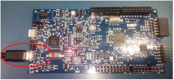
Execute the project on Hardware:
Connect the LPCXpresso4367 board to the USB port of your host computer, connecting a micro USB cable to connector J5 (“Link”).
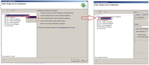
Click on Debug configuration as shown below:

Select “C/C++ (NXP Semiconductors) MCU Application” and select New as shown below:
By clicking new automatically “Periph_timers” project gets selected
Now select on debugger tab and select the below option
Debug connection: SWD
Emulator selection : LinkServer

Connect to the emulator with LinkServer type LPC-Link-2 CMSIS-DAP as shown below:

Now Debug Periph_timers is active and below windows appears:

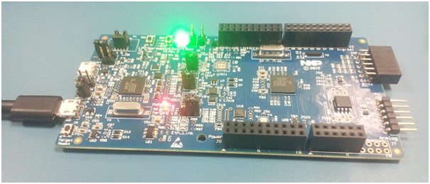
Click on Resume button to run the project. You can see Blue led (RGB) will blink at the rate 10 Hz as defined in timers.c
#define TICKRATE_HZ 10

Changing to Green LED and timer interval
Now let’s change this to blink at 1 Hz i.e at interval of 1 sec
Change TICKRATE_HZ to 1 in timers.c
#define TICKRATE_HZ 1
And we will change instead of blue LED to green LED by changing
Board_LED_Set(0, On); to Board_LED_Set(1, On); which is connected to Port-0, pin- 7 (defined in board.c)
Build the project again and execute the project you will see the led colour changed to Green and the interval rate at which it blinks is 1 second.
Happy working with LPC4367 