This tutorial was extracted from Erich Styger blog http://mcuoneclipse.wordpress.com with his agreement.
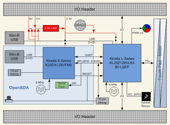
In “Tutorial: Enlightning the Freedom KL25Z Board” I used the RGB LED on the FRDM-KL25Z board. This tutorial extends it to use the Freescale MMA8451QMMA8451Q inertial sensor on the board which is connected through I2C to the Freescale MKL25Z128VLK4MKL25Z128VLK4 microcontroller:
Freedom Board Block Diagram with MMA8451Q (lower right corner)
The goal is show the accelerometer x, y and z-axis on the RGB LED.
I’m using CodeWarrior for MCU V10.3 which has the ARM gcc build tools integrated for the Kinetis family. It is possible to extend the “Tutorial: Enlightning the Freedom KL25Z Board” project and to add the I2C and accelerometer, or starting with a new project. In the steps below I create a new project, but I’m not going into the details how to add the LED as this is explained in the previous tutorial.
Creating the Project
I use the menu File > New > Bareboard Project:
File New Menu to create a new Bareboard project
Next, I need to specify a name for my project:
Naming the project
Next, I select the MKL25Z128 as my device:
Hint: I can use the filter field to at the top of the dialog to filter the devices.
Selecting KL25Z128 with filter text
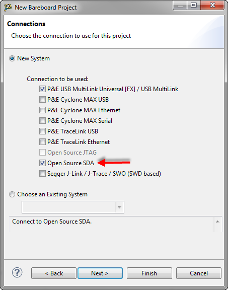
Next, to select the debug connection. As the Freedom Board has the new OpenSDA on it, this is my choice:
OpenSDA Debug Connection
In the next dialog, I can go with the default settings. the ARM GNU GCC is the only (and default) tool-chain for Kinetis L (Cortex M0+) family:
gcc ARM Toolchain
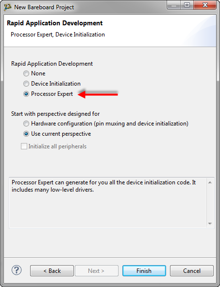
Next, I select Processor Expert for my project:
Processor Expert
Pressing ‘Finish’ creates the project for me:
Freedom Project
RGB LED
How to add the RGB LED support is shown in “Tutorial: Enlightning the Freedom KL25Z Board” so I’m not explaining the details here.
Hint: I can copy-paste components from one project to another project in MCU10.3, even between workspaces. Simply select the component(s), use the ‘copy’ context menu, switch to the other project and past it into the Components group of that project. Really cool!
With the LEDs added, the component list should look something like this:
LED components
I2C
Processor Expert provides an I2C component (I2C_LDD) which implements a driver for it. I make sure that I have my project selected, then I choose in the Components Library view the I2C_LDD and add it to my project:
Adding I2C_LDD
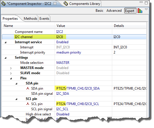
According to the schematics, the accelerometer is on the I2C0 channel (with PTE25 and PTE25), so this is already the default, so no change here:
I2C Channel with pins
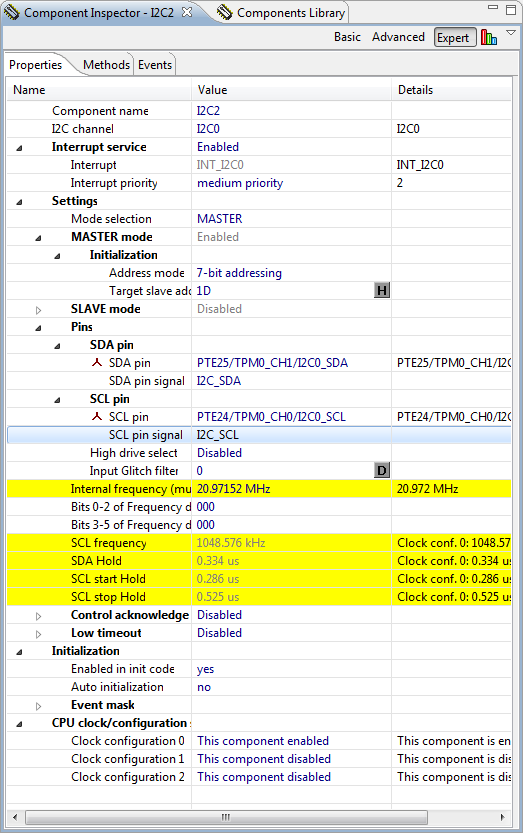
I’m only using the accelerometer on the bus, and the MMA8451QR1MMA8451QR1 is using the (hex) 1D slave address, so I specify this in the properties. To enter hex values, I need to switch the format to the ‘H’ mode:
Target Slave Address
What I need to know the maximum bus clock frequency. The MMA8451QR1MMA8451QR1 Reference guide gives this information:
I2C MMA8451QR1MMA8451QR1 clock speed
And the schematic of the Freedom board has this:
I2C Inertial Sensor Schematics
So we have I2C Pullups with 4.7K Ohm, but Cb is not specified. With 100 KHz I would be on the safe side, but I tried 1 MHz and that worked fine for me:
I2C Clock Settings
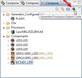
With this, I have my basic settings in place and can generate the driver code:
Generate Driver Code
Accelerometer Interface
Time to write the software ![]() . Using the I2C_LDD, I need to use a device data structure with flags for data received and sent. So I declare this in my header file MMA8451.h:
. Using the I2C_LDD, I need to use a device data structure with flags for data received and sent. So I declare this in my header file MMA8451.h:
01 | /* |
02 | * MMA8451.h |
03 | * Author: Erich Styger |
04 | */ |
05 |
06 | #ifndef MMA8451_H_ |
07 | #define MMA8451_H_ |
08 |
09 | #include "PE_Types.h" |
10 | #include "PE_LDD.h" |
11 |
12 | typedef struct { |
13 | volatile bool dataReceivedFlg; /* set to TRUE by the interrupt if we have received data */ |
14 | volatile bool dataTransmittedFlg; /* set to TRUE by the interrupt if we have set data */ |
15 | LDD_TDeviceData *handle; /* pointer to the device handle */ |
16 | } MMA8451_TDataState; |
17 |
18 | /* \brief Run the demo application */ |
19 | void MMA8451_Run(void); |
20 |
21 | #endif /* MMA8451_H_ */ |
I2C_LDD Events
The I2C_LDD is using events callback. For this I need to set the proper flags in the event:
01 | /* |
02 | ** =================================================================== |
03 | ** Event : I2C2_OnMasterBlockSent (module Events) |
04 | ** |
05 | ** Component : I2C2 [I2C_LDD] |
06 | ** Description : |
07 | ** This event is called when I2C in master mode finishes the |
08 | ** transmission of the data successfully. This event is not |
09 | ** available for the SLAVE mode and if MasterSendBlock is |
10 | ** disabled. |
11 | ** Parameters : |
12 | ** NAME - DESCRIPTION |
13 | ** * UserDataPtr - Pointer to the user or |
14 | ** RTOS specific data. This pointer is passed |
15 | ** as the parameter of Init method. |
16 | ** Returns : Nothing |
17 | ** =================================================================== |
18 | */ |
19 | void I2C2_OnMasterBlockSent(LDD_TUserData *UserDataPtr) |
20 | { |
21 | MMA8451_TDataState *ptr = (MMA8451_TDataState*)UserDataPtr; |
22 |
23 | ptr->dataTransmittedFlg = TRUE; |
24 | } |
25 |
26 | /* |
27 | ** =================================================================== |
28 | ** Event : I2C2_OnMasterBlockReceived (module Events) |
29 | ** |
30 | ** Component : I2C2 [I2C_LDD] |
31 | ** Description : |
32 | ** This event is called when I2C is in master mode and finishes |
33 | ** the reception of the data successfully. This event is not |
34 | ** available for the SLAVE mode and if MasterReceiveBlock is |
35 | ** disabled. |
36 | ** Parameters : |
37 | ** NAME - DESCRIPTION |
38 | ** * UserDataPtr - Pointer to the user or |
39 | ** RTOS specific data. This pointer is passed |
40 | ** as the parameter of Init method. |
41 | ** Returns : Nothing |
42 | ** =================================================================== |
43 | */ |
44 | void I2C2_OnMasterBlockReceived(LDD_TUserData *UserDataPtr) |
45 | { |
46 | MMA8451_TDataState *ptr = (MMA8451_TDataState*)UserDataPtr; |
47 |
48 | ptr->dataReceivedFlg = TRUE; |
49 | } |
Aditionally, I need to include my header file into Events.c:
01 | /** ################################################################### |
02 | ** Filename : Events.c |
03 | ** Project : ProcessorExpert |
04 | ** Processor : MKL25Z128VLK4 |
05 | ** Component : Events |
06 | ** Version : Driver 01.00 |
07 | ** Compiler : GNU C Compiler |
08 | ** Date/Time : 2012-08-23, 07:09, # CodeGen: 0 |
09 | ** Abstract : |
10 | ** This is user's event module. |
11 | ** Put your event handler code here. |
12 | ** Settings : |
13 | ** Contents : |
14 | ** Cpu_OnNMIINT - void Cpu_OnNMIINT(void); |
15 | ** |
16 | ** ###################################################################*/ |
17 | /* MODULE Events */ |
18 |
19 | #include "Cpu.h" |
20 | #include "Events.h" |
21 |
22 | /* User includes (#include below this line is not maintained by Processor Expert) */ |
23 | #include "MMA8451.h" |
Accelerometer Implementation
For this I create a file MMA8451.c with routines to read and write accelerometer registers:
01 | /* |
02 | * MMA8451.c |
03 | * Author: Erich Styger |
04 | */ |
05 | #include "MMA8451.h" |
06 | #include "I2C2.h" |
07 | #include "LED1.h" |
08 | #include "LED2.h" |
09 | #include "LED3.h" |
10 |
11 | /* External 3-axis accelerometer control register addresses */ |
12 | #define MMA8451_CTRL_REG_1 0x2A |
13 | /* MMA8451QR1MMA8451QR1 3-axis accelerometer control register bit masks */ |
14 | #define MMA8451_ACTIVE_BIT_MASK 0x01 |
15 | #define MMA8451_F_READ_BIT_MASK 0x02 |
16 |
17 | /* External 3-axis accelerometer data register addresses */ |
18 | #define MMA8451_OUT_X_MSB 0x01 |
19 | #define MMA8451_OUT_X_LSB 0x02 |
20 | #define MMA8451_OUT_Y_MSB 0x03 |
21 | #define MMA8451_OUT_Y_LSB 0x04 |
22 | #define MMA8451_OUT_Z_MSB 0x05 |
23 | #define MMA8451_OUT_Z_LSB 0x06 |
24 |
25 | static MMA8451_TDataState deviceData; |
26 |
27 | uint8_t MMA8451_ReadReg(uint8_t addr, uint8_t *data, short dataSize) { |
28 | uint8_t res; |
29 |
30 | /* Send I2C address plus register address to the I2C bus *without* a stop condition */ |
31 | res = I2C2_MasterSendBlock(deviceData.handle, &addr, 1U, LDD_I2C_NO_SEND_STOP); |
32 | if (res!=ERR_OK) { |
33 | return ERR_FAILED; |
34 | } |
35 | while (!deviceData.dataTransmittedFlg) {} /* Wait until data is sent */ |
36 | deviceData.dataTransmittedFlg = FALSE; |
37 |
38 | /* Receive InpData (1 byte) from the I2C bus and generates a stop condition to end transmission */ |
39 | res = I2C2_MasterReceiveBlock(deviceData.handle, data, dataSize, LDD_I2C_SEND_STOP); |
40 | if (res!=ERR_OK) { |
41 | return ERR_FAILED; |
42 | } |
43 | while (!deviceData.dataReceivedFlg) {} /* Wait until data is received received */ |
44 | deviceData.dataReceivedFlg = FALSE; |
45 | return ERR_OK; |
46 | } |
47 |
48 | uint8_t MMA8451_WriteReg(uint8_t addr, uint8_t val) { |
49 | uint8_t buf[2], res; |
50 |
51 | buf[0] = addr; |
52 | buf[1] = val; |
53 | res = I2C2_MasterSendBlock(deviceData.handle, &buf, 2U, LDD_I2C_SEND_STOP); /* Send OutData (3 bytes with address) on the I2C bus and generates not a stop condition to end transmission */ |
54 | if (res!=ERR_OK) { |
55 | return ERR_FAILED; |
56 | } |
57 | while (!deviceData.dataTransmittedFlg) {} /* Wait until date is sent */ |
58 | deviceData.dataTransmittedFlg = FALSE; |
59 | return ERR_OK; |
60 | } |
RGB Demo
What is missing is the demo code itself. I keep things simple here, and turn on one of the LEDs if the acceleration on an axis is exceeding a threshold:
01 | static int8_t xyz[3]; |
02 |
03 | void MMA8451_Run(void) { |
04 | uint8_t res; |
05 |
06 | LED1_On(); |
07 | LED2_On(); |
08 | LED3_On(); |
09 | deviceData.handle = I2C2_Init(&deviceData); |
10 | /* F_READ: Fast read mode, data format limited to single byte (auto increment counter will skip LSB) |
11 | * ACTIVE: Full scale selection |
12 | */ |
13 | res = MMA8451_WriteReg(MMA8451_CTRL_REG_1, MMA8451_F_READ_BIT_MASK|MMA8451_ACTIVE_BIT_MASK); |
14 | if (res==ERR_OK) { |
15 | for(;;) { |
16 | res = MMA8451_ReadReg(MMA8451_OUT_X_MSB, (uint8_t*)&xyz, 3); |
17 | LED1_Put(xyz[0]>50); |
18 | LED2_Put(xyz[1]>50); |
19 | LED3_Put(xyz[2]>50); |
20 | } |
21 | } |
22 | I2C2_Deinit(deviceData.handle); |
23 | LED1_Off(); |
24 | LED2_Off(); |
25 | LED3_Off(); |
26 | } |
Calling from main()
And the last piece is to call my demo routine from main():
01 | /** ################################################################### |
02 | ** Filename : ProcessorExpert.c |
03 | ** Project : ProcessorExpert |
04 | ** Processor : MKL25Z128VLK4 |
05 | ** Version : Driver 01.01 |
06 | ** Compiler : GNU C Compiler |
07 | ** Date/Time : 2012-08-23, 07:09, # CodeGen: 0 |
08 | ** Abstract : |
09 | ** Main module. |
10 | ** This module contains user's application code. |
11 | ** Settings : |
12 | ** Contents : |
13 | ** No public methods |
14 | ** |
15 | ** ###################################################################*/ |
16 | /* MODULE ProcessorExpert */ |
17 |
18 | /* Including needed modules to compile this module/procedure */ |
19 | #include "Cpu.h" |
20 | #include "Events.h" |
21 | #include "LED1.h" |
22 | #include "LED2.h" |
23 | #include "LED3.h" |
24 | #include "GPIO1.h" |
25 | #include "GPIO2.h" |
26 | #include "I2C2.h" |
27 | /* Including shared modules, which are used for whole project */ |
28 | #include "PE_Types.h" |
29 | #include "PE_Error.h" |
30 | #include "PE_Const.h" |
31 | #include "IO_Map.h" |
32 |
33 | /* User includes (#include below this line is not maintained by Processor Expert) */ |
34 | #include "MMA8451.h" |
35 |
36 | int main(void) |
37 | { |
38 | /* Write your local variable definition here */ |
39 |
40 | /*** Processor Expert internal initialization. DON'T REMOVE THIS CODE!!! ***/ |
41 | PE_low_level_init(); |
42 | /*** End of Processor Expert internal initialization. ***/ |
43 |
44 | /* Write your code here */ |
45 | MMA8451_Run(); |
46 |
47 | /*** Don't write any code pass this line, or it will be deleted during code generation. ***/ |
48 | /*** RTOS startup code. Macro PEX_RTOS_START is defined by the RTOS component. DON'T MODIFY THIS CODE!!! ***/ |
49 | #ifdef PEX_RTOS_START |
50 | PEX_RTOS_START(); /* Startup of the selected RTOS. Macro is defined by the RTOS component. */ |
51 | #endif |
52 | /*** End of RTOS startup code. ***/ |
53 | /*** Processor Expert end of main routine. DON'T MODIFY THIS CODE!!! ***/ |
54 | for(;;){} |
55 | /*** Processor Expert end of main routine. DON'T WRITE CODE BELOW!!! ***/ |
56 | return 0; |
57 | } /*** End of main routine. DO NOT MODIFY THIS TEXT!!! ***/ |
58 |
59 | /* END ProcessorExpert */ |
60 | /* |
61 | ** ################################################################### |
62 | ** |
63 | ** This file was created by Processor Expert 10.0 [05.02] |
64 | ** for the Freescale Kinetis series of microcontrollers. |
65 | ** |
66 | ** ################################################################### |
67 | */ |
Accelerometer In Action
If I place the board flat on the table, the blue LED is on:
Blue LED
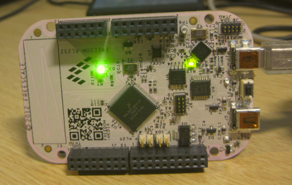
With the board on the side, the green LED is on:
Green LED
And with the board standing up, the red LED is on:
Red LED
The current software was attached to this document but I would recommend to download the updated version on GitHub with all the Processor Expert components.

