

This tutorial was extracted from Erich Styger blog http://mcuoneclipse.wordpress.com with his agreement.
One of my embedded projects is to measure the running time in a sports event (see “Sports Timing System in a Lunch Box“). The recorded time is stored in an EEPROM plus sent over USB or wireless connection to the host. It would be great if I could print out the time and ranking directly, so if there is no PC, the system can be small and tiny. So here is my next project and tutorial: Printing with the Freedom board!

Hello World on the Printer with FRDM-KL25Z
The ability to print is a great addition to any other project: I can send messages to be printed out on a remote board, using it as a receipt printer, logging test results and many more things: having printing capabilities is such a great addition to any project, and it does not take much! I have spent this Sunday morning only 4 hours from unpacking, connecting the hardware, programming the first software with CodeWarrior+Processor Expert until I had a “Hello World from the FRDM-KL25Z!” showing up on the printer! And that 4 hours included writing this tutorial. So expect it would take you less than one hour with the help of this tutorial.

First Hello World Message on Printer
Adafruit Mini Thermal Receipt Printer
I ordered a small thermal printer from Adafruit (http://learn.adafruit.com/mini-thermal-receipt-printer) which costs $50. I added three thermal paper rolls (http://www.adafruit.com/products/599) to my order to have enough paper to start with :-):
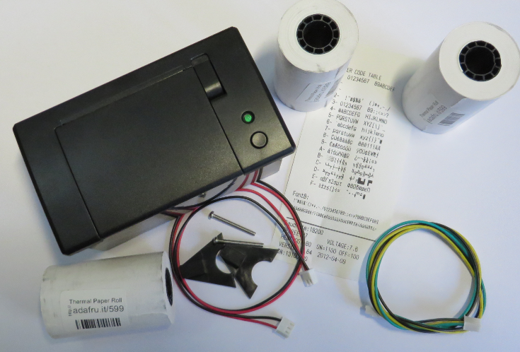
Adafruit Mini Thermal Printer unpacked
The main features of the printer (from the data sheet):
- Thermal paper printer, 2.25″/57mm wide (effective printing width 48 mm)
- Built-in fonts: small, medium, large text
- Bold, underline and inverted text with left/right/center positioning
- Different bar codes
- Printing monochrome bitmaps and images
- Size: 111x65x57 mm
- 5-9V DC, 1.5 A
- TTL Serial (RS-232, 5V) protocol
Useful links:
- Printer data sheet:http://www.adafruit.com/datasheets/cashino%20thermal%20printer%20a2.pdf
- Printer user manual: http://www.adafruit.com/datasheets/A2-user%20manual.pdf
- Adafruit Thermal Printer Overview: http://learn.adafruit.com/mini-thermal-receipt-printer/overview
With the printer came a test print which has the baud listed. There are printers with 9600 baud and others with 19200, mine came with 19200. More about this later.

Printer Test Print with Baudrate
Mounting and Connectors
The two brackets are for mounting the printer behind a panel. In order not to lose the parts, I mounted them right away:

Adding Printer Mounting Brackets
The cables get connected to the backside of the printer:

Printer Backside Connectors
Power Supply
The printer requires a 5-9V power supply. Thermal printing needs a lot of power, so a 1.5 amps power supply is needed! There are many ways how you could give power to the printer. I usually have always a bunch of power supplies, but the challenges is that the plugs never match my needs. So usually I end up cutting the wires and making it fitting my needs. For this project I use a 5V 2A power supply I have left over from a damaged Cisco router:

5V 2A Power Supply
I cut the 5V wires:

Power Supply 5V Wires cut
Same for the printer supply wires:
:!: Cut the wires on the 2-pin connector (NOT on the 3-pin side)!

Cutting Printer Supply Wires
Then remove the isolation:

Removed Isolation
I’m using heat shrink tubes for isolation, but you can use electrical isolation tape too (not so nice as heat shrink tubes). I cut pieces of different diameter and size:

Shrink Tubes
Put them on the wire before soldering:

Shrink Tubes on Wires
Wrap the wires together:
:!: carefully check the wire polarity (what is plus, and what is ground)! In doubt, use a voltage meter to verify it!

Wires Wrapped together
Solder the wires:

Solder the Wires
Then use a hot air gun to shrink it:

Shrinking with Hot Air Gun
The result is a nice connection:

Shrinked Power Cable
Inserting Paper
When powered, the green LED flashes. There is a ‘Paper Feed’ button plus a lever to open the printer.

Printer button, LED and lever
A roll presses the paper on the printer head:

Paper Press Roll
The printer head is near the ‘cut off’ area:

Printer Head
The paper is placed inside the printer. Make sure the paper is clean and has no stickers/etc on it:

Paper inside the printer
Then close the cover:

Printer Cover Closed
Making a Test Print
Powering the printer with the ‘paper feed’ button pressed will print a test report:

Test Print with Baudrate
Now I’m sure my printer is working :-)
Printer Connection to the FRDM Board
There is problem: the printer uses 5V (TTL) logic levels, while my FRDM board has 3.3V levels. The printer accepts 3.3V input values (on the printer RX line), but it would be a bad idea to connect the printer output 5V TX signal to a microcontroller having 3.3V levels without a level shifter.

Printer Tx and Rx
As I’m only sending data to the printer, I’m *not* going to connect the printer 5V Tx line to my board. I’m only connecting the GND and the microcontroller Tx with the Printer Rx. For this I’m using connector cables:

Printer to Microcontroler Connection
Ground is connected to the board GND pin. I’m free to use any available UART Tx pin, and I have used UART0 Tx (Port A, pin 2) PTA2:

FRDM-KL25Z Connections
Summary
In few hours, I have now the ability to print at least some text, using the FRDM-KL25Z and the Adafruit thermal receipt printer. Much faster than I have expected, which is a great thing. Time for having lunch. A next post will be about how to use the software.
But if you cannot wait: the project is already on GitHub:https://github.com/ErichStyger/mcuoneclipse/tree/master/Examples/FRDM-KL25Z/FRDM-KL25Z_Printer
Happy Printing :-)