

This Project brings you with a quick step in blinking an LED on FRDM-KL46ZFRDM-KL46Z board using Processor Expert.
The Freescale Freedom development platform is a set of software and hardware tools for evaluation and development. It is ideal for rapid prototyping of microcontroller-based applications. The Freescale Freedom KL46Z hardware, FRDM-KL46ZFRDM-KL46Z, is a simple, yet sophisticated design featuring a Kinetis L series microcontroller, built on the ARM Cortex
 -M0+ core.
FRDM-KL46Z can be used to evaluate the KL46, KL36, KL26 and KL16 Kinetis L series devices. It features a MKL46Z256VLL4MKL46Z256VLL4, this device boasting a max operating frequency of 48MHz, 256KB of flash, 32KB RAM, a full-speed USB controller, segment LCD controller, and loads of analog and digital peripherals. The FRDM-KL46Z hardware is form-factor compatible with the Arduino R3 pin layout, providing a broad range of expansion board options. The on-board interfaces includes a 4 digit segment LCD, a 3-axis digital accelerometer, magnetometer, capacitive touch slider, and ambient light sensor.
The FRDM-KL46Z features the Freescale open standard embedded serial and debug adapter known as OpenSDA. This circuit offers several options for serial communications, flash programming and run-control debugging.
Refer to the link for more details on Freedom board.
The features of the FRDM-KL46ZFRDM-KL46Z include:
- MKL46Z256VLLZ4MKL46Z256VLLZ4 MCU (48 MHz, 256 KB Flash, 32 KB RAM, Low power, 100 LQFP package)
- Dual role USB interface with mini-B USB connector
- Open SDA
- 4 digit segment LCD module
- Capacitive touch slider
- Ambient light sensor
- MMA8451QMMA8451Q accelerometer
- MAG3110MAG3110 Magnetometer
- 2 user LEDs
- 2 user push buttons
- Flexible power supply options – USB, coin cell battery, external source
- Battery-ready, power-measurement access points
- Easy access to MCU I/O via Arduino R3 compatible I/O connectors
- Programmable OpenSDA debug interface with multiple applications available including:
- Mass storage device flash programming interface
- P&E Debug interface provides run-control debugging and compatibility with IDE tools
- CMSIS-DAP interface: new ARM standard for embedded debug interface
- Data logging application
- Arduino R3 compatibility
Before we start on our project make sure the board is in Debug mode (refer to the blog how to load in Debug mode using OpenSDA)
Now that our board is loaded in Debug Let’s start on creating a CodeWarrior project to quickly demonstrate blinking LED on KL46 board.
A free version of Codewarrior can be downloaded following the link below in the Downloads section:
The Evaluation version is a 30 days Limited version and the Special Edition is Code Size Limited version (64KB for Kinetis MCUs with an ARM Cortex-M0+ core and 128KB for the Kinetis MCUs with an ARM Cortex-M4 core).
Follow the below steps for creating the CW project:
Select File->New->Bareboard Project

Provide Project Name “Blink it using PE-KL46” then click Next

Now select the MCU exist on our KL46 board it is “MKL46Z256”
Kinetis L Series-> KL4x Family->KL46Z(48 MHz) Family->MKL46Z256
then Click Next

Select OpenSDA option to connect for this board for debugging and programming, then click Next

Then click Next to proceed further

Select ‘Processor Expert’ option as we are creating the project using Processor Expert then click ‘Finish’

I have created the project by name “Blink it using PE-KL46” as shown below are the component inspector showing CPU with default settings:

First we need to configure CPU parameter settings as shown below:

Under clock Settings->
System Oscillator: Enabled
Clock Source: External Oscillator
Clock Frequency: 8 MHz (as this board is connected to external crystal oscillator )
Under clock source settings-> clock source settings 0-> MCG settings->
MCG mode: FEI (FLL engaged internal)
FLL settings->FLL output[MHz] : 47.972352
Then automatically MCG output[MHz] gets selected to 47.972352
Then under Clock configurations->Clock configuration 0->System clocks->
Set
Core clock: 47.972352 MHz
Bus clock: 23.986176 MHz
Then all other parameters which were highlighted in RED gets cleared which means the settings are correct. These settings are as shown in above figure.
Since now our project skeleton is ready (i.e no component module peripherals has been added to our project) we need to add the required peripheral component module as per our requirement.
Our requirement here is to blink the LED present in KL46 board; refer to below schematic there are two LED’s exist on board Red and Green connected to Port-E 29th bit (PTE29) and Port-D 5th bit (PTD5).
|
LED |
KL46 |
|
Green (LED1) |
PTD5 |
|
Red (LED2) |
PTE29 |


We now need to add two component modules for these two led’s those are as shown below
Now select under Component Library-> categories sub window
Click on Logical Device Drivers->Port I/O-> BitIO_LDD
Right click and select ‘Add to Project’ twice since we need two LED component in our project.

Now we are adding software generated ‘wait’ component in order to add delay routine to our project.
Under Component Library-> categories sub window
Click on SW->User Components->Wait component, Right click and select ‘Add to Project’


Rename the components (LED_RED, LED_Green, WAIT1)as shown below:

Make the ‘LED_RED’ BitIO settings as shown below: assigned to output pin ‘PTE29’

Make the ‘LED_Green’ BitIO settings as shown below: assigned to output pin ‘PTD5’

And default settings for ‘Wait1’ component as shown below:

Now click on ‘Generate Processor Expert code’ radio button as shown below:

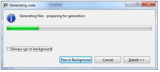
You can see the tool generates required code as shown below:
All the required header files will get generated under ‘Generated_Code’ folder as shown below:

Now select ‘ProcessorExpert.c’ from project window

Add below lines of code in ‘ProcessorExpert.c’ file
int main(void)
/*lint -restore Enable MISRA rule (6.3) checking. */
{
/* Write your local variable definition here */
/*** Processor Expert internal initialization. DON'T REMOVE THIS CODE!!! ***/
PE_low_level_init();
/*** End of Processor Expert internal initialization. ***/
LDD_TDeviceData *Led_RPtr, *Led_GPtr;
Led_RPtr = LED_RED_Init((LDD_TUserData *)NULL);
Led_GPtr = LED_Green_Init((LDD_TUserData *)NULL);
/* Write your code here */
/* For example: for(;;) { } */
while(1)
{
LED_RED_ClrVal(Led_RPtr);
LED_Green_ClrVal(Led_GPtr);
WAIT1_Waitms(1000);
LED_RED_SetVal(Led_RPtr);
LED_Green_SetVal(Led_GPtr);
WAIT1_Waitms(500);
}
/*** Don't write any code pass this line, or it will be deleted during code generation. ***/
/*** RTOS startup code. Macro PEX_RTOS_START is defined by the RTOS component. DON'T MODIFY THIS CODE!!! ***/
#ifdef PEX_RTOS_START
PEX_RTOS_START(); /* Startup of the selected RTOS. Macro is defined by the RTOS component. */
#endif
/*** End of RTOS startup code. ***/
/*** Processor Expert end of main routine. DON'T MODIFY THIS CODE!!! ***/
for(;;){}
/*** Processor Expert end of main routine. DON'T WRITE CODE BELOW!!! ***/
} /*** End of main routine. DO NOT MODIFY THIS TEXT!!! ***/
/* END ProcessorExpert */
The functions related to LED_RED, LED_Green can be explored from the Generated code folder in “LED_RED.c”, “LED_Green.c” and defined in LED_RED.h, LED_Green.h files as shown below:

Its functions can also be seen from components window as shown:

As per the code instruction we are turning on LED for 1000 ms and turning off the LED’s for 500 ms and looping forever.
Now it’s time to clean and Build the project as shown:

You can then see project starts building as shown:

Now Run the project as shown:

Now you can see the blinking of Red and Green LED on KL46 board

Created Project folder and output video file is attached in this tutorial for quick reference.
Happy Blinking LED on PE.....
