

“This tutorial was extracted from Erich Styger blog http://mcuoneclipse.wordpress.com with his agreement.”
The Freescale FRDM-K64F is a great board for data logger applications: it has a powerful ARM Cortex M4F with 120 MHz, 1 MB Flash and 256 KByte RAM. Best of all: it already has a micro SD card socket on the board 

Data Logger with FRDM-K64F
Outline
In “Arduino Data-Logger Shield with the FRDM-KL25Z Board” I already used the FRDM-KL25Z with the Arduino Data-Logger shield with CodeWarrior. Basically the same can be applied to the FRDM-K64F. I moved to Eclipse Kepler (see “Constructing a Classroom IDE with Eclipse for ARM“), so here is an updated tutorial: how to create a data logger application with the FRDM-K64F and Eclipse Kepler.
You need:
- Eclipse Kepler with Processor Expert as outlined in “Constructing a Classroom IDE with Eclipse for ARM“
- Freescale FRDM-K64F board with USB cable
- A micro SD card
: This tutorial can be used with CodeWarrior for MCU10.x, Processor Expert Driver Suite or Kinetis Design Studio too. The principle is the same, but the project creation steps will be somewhat different.

Make sure you have loaded the latest Processor Expert components from GitHub (see “Processor Expert Component *.PEupd Files on GitHub“).The project created in this tutorial is available on GitHub:https://github.com/ErichStyger/mcuoneclipse/tree/master/Examples/Eclipse/FRDM-K64F/FRDM-K64F120M/FRDM-K64F_DataLogger.In principle, this tutorial can be applied to any other board: Just make sure you select the microcontroller on your board, and adopt the pin settings for the devices you have.While it would make sense to use an RTOS like FreeRTOS for a data logger, I’m showing here a ‘bare metal’ data logger. An RTOS with tasks then can be easily added to the project.
Creating the Project
Use the menu File > New > C Project to create a new

New Project
Provide a name for the Cross ARM GCC Freescale Processor Expert C/C++ Project:

DataLogger Cross ARM GCC Project for Processor Expert
Then select the M4 core with the PEx Driver Suite 10.4 Wizard invocation:

M4 core for PEx DriverSuite 10.4
In the next dialog I usually deselect the ‘Release’ configuration:

Debug only
In the next dialog I have the opportunity to configure the tool chain.

Cross GNU ARM Toolchain
Press ‘Finish’, and the project wizard calls the Processor Expert wizard to configure the microcontroller. Select the MK64FN1M0xxx12 which is present on the FRDM-K64F board:
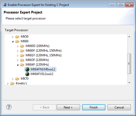
MK64FN1M0xxx12
In the next dialog I use ‘Linked’: this means that the project uses links to the Processor Expert library files. Alternatively you can use ‘Standalone’, then the files get copied into the project.

Linked Mode
Then I select the GNU C Compiler:

GNU C Compiler
With ‘Finish’ the project gets created. Processor Expert opens a help window explaining how to convert a project for Processor Expert. We can ignore this as the wizard already has done everything for us

DataLogger Project
Project Cleanup and Adjustments
While the project created is fine, I usually do some cleanup. First I remove the ‘RAM’ configuration with the context menu, as I’m only going to use the FLASH target:

Deleting Configuration
Same for the obsolete CPU (orphaned now as it was tight to the RAM configuration

Removing RAM Configuration CPU
The MK64FN1M0VLQ12 derivative is a LQFP 144-pin package, but the FRDM-K64F board is using a LQFP 100-pin package. In the component inspector, I change it to the 100-pin package:

Changing CPU package
The PinSettings component can be removed, as we will care ourselves about the pin settings in the components:

PinSettings Component
Now the project is clean and using the 100-pin VLL12 package:

100-pin VLL12 package
Generating Code
The project is still ‘empty’, but at this stage I prefer to verify that I can generate code, build it and download it to the target. To generate the Processor Expert code I use the toolbar icon:

Generate Processor Expert Code
Building Project
To build the project I select the project and use the ‘Hammer’ drop down icon:

Building Project
It should build with no errors:

Console View with no Errors
Debugging
I’m using here the Segger OpenSDAv2 debug firmware on the FRDM-K64F board. I select the project and open the Debug Configurations:

Menu Debug Configurations
The double-click on the GDB Segger J-Link Debugging item to create a new configuration: The .elf and project name should be filled automatically:

New Segger Launch Configuration
In the Debugger tab I make sure the proper device name (MK64FN1M0xxx12) and interface (SWD) is selected:
Device name and interface for Segger
In the Startup tab I make sure semihosting and SWO are disabled:
Segger Semihosting and SWO disabled
Pressing Apply (if any changes), then press Debug to launch the debugger, and I should be debugging:
Initial Debug Session
So with this I know that everything works from building to debugging. Time to terminate the debugging session:
Terminating the debug session
And to return to the C/C++ perspective:

Return to C and C++ Perspective
FatFS File System
To use the SD card with the FAT file system, I add the FatFS component to the project:As to write files to the file system I need date/time information, it asks me to add a clock component. I select the GenericTimeDate component:
Adding GenericTimeDate Component
Next, FatFS needs a memory component, and here I select the SD_Card component:

Adding Memory Component for FatFS
To protect the critical sections, it asks me to select the component I want to use. It already should have added a Critical Section (CS1) component, so I go with the CS1 choice:

Linking to CS1 component
With this, I have new components added to my project. Some with a red X indicate that some settings are missing:
FatFS Components added
I need to configure the pins for the SPI which talks to the SD card. For this I open the Component inspector for the SPI component:
Need to configure the SPI
As the SD card on the board is connected to SPI1, I choose SPI1 as device with
- MISO/Input pin: PTE1
- MOSI/Output pin: PTE3
- SCLK/Clock pin: PTE2
- and no chip select list (use the ‘-’ button to remove it)

MISO, MOSI, Clock and chip select
The chip select list is not needed as the FatFs component will handle the chip select on its own. Scrolling down I need to configure the clock details. For this I clock on the ‘…’:

Configuring the clock
From the available timings, I double-click from the list on the right hand side to have a value assigned:
Selecting timing value
Then press OK, and do the same for the three delay timing needed:

Delay timing assigned
For the clock rate we not only need one timing, but three: initial/low and high-speed. Again clicking on the ‘…’ for the Clock rate to open the dialog.I want to assign values in kHz, so I select that from the Unit drop down list (click into the Value field to have it updated):
Clocks in kHz
As I need two values, I configure it as ‘List of values’:

List of Values
Then I assign for the low value a maximum value of 375 kHz, and for high I can go up to 12 MHz (my clock configuration only allows 10 MHz max

SPI Clock Values
Pressing OK to close the SPI clock configuration. To use the two configurations, I need to add a second attribute set. Because the ‘Tabs View’ uses a lot of screen real estate, it is easier if I switch to the ‘classic’ non-tabs view (small triangle in view toolbar to reach the menu

Disabling Tabs View
Next step is to enable the automatic initialization of the SPI component:
Automatic initialization of the SPI component
I click into the Attribute set list box (where the ’1′ is) and click on the ‘+’:
Adding New Attribute Set
Then specify that the SPI clock index 1 shall be used:

Clock Rate Index for Attribute Set 1
In the SD_Card Component, I need to specify that it can use the index 1 (10 MHz) for fast mode:

Fast Baud Rate Mode
I order to be able to switch different clock configurations, I need to enable the method SelectConfiguration():Next I need to assign the chip select pin. This is inside the SD_Card component:

Need to configure SPI Chip Select
The chip select is on PTE4. I can click into the field and type in the name (or to select from the list) to assign it:
Assigning PTE4 as Chip Select
Next we add the card detection (CD) pin: I select the SD_Card component and enable the pin:
Enable Card Detection Pin
On the FRDM-K64F, the card detection is HIGH active, so I need to deselect the ‘Card Detect is LOW active’:
Card Detect Low or High Active
Realtime Clock
For the SD card I need a realtime clock. Our board does not have this, but I have configured a software realtime clock: GenericTimeDate. As in this tutorial I’m not going to use an RTOS, I add a TimerInt component to the project and configure it for 10 ms:

TimerInt component
I need to call the AddTick() method of the realtime clock every 10 ms from above interrupt:

Realtime Clock AddTick() Method
So I generate code:

Generate Code
Then I double-click on the OnInterrupt() event to open the Events.c source file with that event created:

Timer OnInterrupt()
Then I can drag&drop the AddTick() method to the source:

Drag and Drop AddTick() Method
Then save the source changes:

Save Source Changes
The data to log: Accelerometer
With the FatFS I have everything to read and write the SD card. Only the data is missing. In this tutorial I’m using the accelerometer of the FRDM-K64F. So I’m adding the FXOS8700CQ component to the project.It will ask for the Wait component (which already is part of the project) and automatically adds the GenericI2C component to it. I enable the LDD I2C and add a new I2C_LDD component:
Adding I2C_LDD with FXOS8700CQ
The I2C_LDD component gets configured for I2C0, SDA (PTE25) and SCL (PTE24), with a clock configuration below 100 kHz:

Accelerometer I2C Configuration
Important and not to forget: according to the schematics, the SA1 is LOW and SA0 pin is HIGH, so the device has the address 0x1D:

Accelerometer Slave Address
With this, the hardware configuration is completed, and I can write the application code .
Application Code
I add a header file Application.h (context menu with File > New > Header File) and source file Application.c (context menu File > New Source File) to the Sources folder:

Application Files
The header file needs only one function:
/*
* Application.h
*/
#ifndef APPLICATION_H_
#define APPLICATION_H_
voidAPP_Run(void);
#endif /* APPLICATION_H_ */
In main.c, I include that header file and call APP_Run:

Main.c calling application
APP_Run() implements my logger loop: initialize the accelerometer and mount the file system. Then it gets the accelerometer data and logs it to a file every second.First, I need to make sure I have a pull-down enabled for the SD card detection pin (PTE6). Because the BitIO component has no methods to change the electrical characteristics, I’m using PDD macros (see “Low-Level Coding with PDD (Physical Device Driver)”)
/* SD card detection: PTE6 with pull-down! */
PORT_PDD_SetPinPullSelect(PORTE_BASE_PTR, 6, PORT_PDD_PULL_DOWN);
PORT_PDD_SetPinPullEnable(PORTE_BASE_PTR, 6, PORT_PDD_PULL_ENABLE);
For the file system I need to have a file system object and a file pointer. To keep things simple, I’m using global variables:
staticFAT1_FATFS fileSystemObject;
staticFIL fp;
The APP_Run() is implemented as below:
void APP_Run(void) {
  int16_t x,y,z;
  uint8_t res;

  /* SD card detection: PTE6 with pull-down! */
  PORT_PDD_SetPinPullSelect(PORTE_BASE_PTR, 6, PORT_PDD_PULL_DOWN);
  PORT_PDD_SetPinPullEnable(PORTE_BASE_PTR, 6, PORT_PDD_PULL_ENABLE);

  res = FX1_Enable(); /* enable accelerometer (just in case) */
  if (res!=ERR_OK) {
    Err();
  }
  if (FAT1_Init()!=ERR_OK) { /* initialize FAT driver */
    Err();
  }
  if (FAT1_mount(0, &fileSystemObject) != FR_OK) { /* mount file system */
    Err();
  }
  for(;;) {
    /* get accelerometer values */
    x = FX1_GetX();
    y = FX1_GetY();
    z = FX1_GetZ();
    /* log it to the file on the SD card */
    LogToFile(x, y, z);
    /* do this every second */
    WAIT1_Waitms(1000);
  }
}
The Err() function is used to indicate an error condition. I can show an error with LED’s or I simply stop application there:
static void Err(void) {
  for(;;){}
}
I want to append the accelerometer data to a file, with date/time information, separated with TABs so I can easily import it into Excel. To construct the strings, I’m going to use the Utility component, so I have added it to my project:

Utility Component
With this, I write my data to the SD card in LogToFile():
- Open the log file (FAT1_open()) with FA_OPEN_ALWAYS (open the file if it already exists, otherwise create the file) and for writing (FA_WRITE).
- Move the file pointer to the end of the file to append the data (FAT1_lseek()).
- Get the current time information from the software realtime clock (TmDt1_GetTime()).
- Construct in a buffer the string to write with time and accelerometer data.
- Write it to the file with FAT1_write().
- Close the file with FAT1_close().
static void LogToFile(int16_t x, int16_t y, int16_t z) {
  uint8_t write_buf[48];
  UINT bw;
  TIMEREC time;

  /* open file */
  if (FAT1_open(&fp, "./log.txt", FA_OPEN_ALWAYS|FA_WRITE)!=FR_OK) {
    Err();
  }
  /* move to the end of the file */
  if (FAT1_lseek(&fp, fp.fsize) != FR_OK || fp.fptr != fp.fsize) {
    Err();
  }
  /* get time */
  if (TmDt1_GetTime(&time)!=ERR_OK) {
    Err();
  }
  /* write data */
  write_buf[0] = '\0';
  UTIL1_strcatNum8u(write_buf, sizeof(write_buf), time.Hour);
  UTIL1_chcat(write_buf, sizeof(write_buf), ':');
  UTIL1_strcatNum8u(write_buf, sizeof(write_buf), time.Min);
  UTIL1_chcat(write_buf, sizeof(write_buf), ':');
  UTIL1_strcatNum8u(write_buf, sizeof(write_buf), time.Sec);
  UTIL1_chcat(write_buf, sizeof(write_buf), '\t');

  UTIL1_strcatNum16s(write_buf, sizeof(write_buf), x);
  UTIL1_chcat(write_buf, sizeof(write_buf), '\t');
  UTIL1_strcatNum16s(write_buf, sizeof(write_buf), y);
  UTIL1_chcat(write_buf, sizeof(write_buf), '\t');
  UTIL1_strcatNum16s(write_buf, sizeof(write_buf), z);
  UTIL1_strcat(write_buf, sizeof(write_buf), (unsigned char*)"\r\n");
  if (FAT1_write(&fp, write_buf, UTIL1_strlen((char*)write_buf), &bw)!=FR_OK) {
    (void)FAT1_close(&fp);
    Err();
  }
  /* closing file */
  (void)FAT1_close(&fp);
}
All what is missing now is the include of the needed header files at the beginning of Application.c:
#include "Application.h"
#include "WAIT1.h"
#include "FX1.h"
#include "FAT1.h"
#include "UTIL1.h"
#include "PORT_PDD.h"
Result
Time to generate code, build and then debug. And it writes file log.txt to the card I can import into Excel:

Data imported in Excel
And visualized in a chart:

Visualized Data
Summary
Writing a data logger is not that difficult with Processor Expert components. As there are many complex components (file system, SPI, I2C, accelerometer) and drivers involved, it takes some time to set everything up. But once understood, it is very easy to have such a data logger implemented easily for any other hardware.
The tutorial project (with minor extensions) is available on GitHub as reference implementation:https://github.com/ErichStyger/mcuoneclipse/tree/master/Examples/Eclipse/FRDM-K64F/FRDM-K64F_DataLogger
Happy Logging