element14 Community
element14 Community
    Register Log In
  • Site
  • Search
  • Log In Register
  • About Us
  • Community Hub
    Community Hub
    • What's New on element14
    • Feedback and Support
    • Benefits of Membership
    • Personal Blogs
    • Members Area
    • Achievement Levels
  • Learn
    Learn
    • Ask an Expert
    • eBooks
    • element14 presents
    • Learning Center
    • Tech Spotlight
    • STEM Academy
    • Webinars, Training and Events
    • Learning Groups
  • Technologies
    Technologies
    • 3D Printing
    • FPGA
    • Industrial Automation
    • Internet of Things
    • Power & Energy
    • Sensors
    • Technology Groups
  • Challenges & Projects
    Challenges & Projects
    • Design Challenges
    • element14 presents Projects
    • Project14
    • Arduino Projects
    • Raspberry Pi Projects
    • Project Groups
  • Products
    Products
    • Arduino
    • Avnet Boards Community
    • Dev Tools
    • Manufacturers
    • Multicomp Pro
    • Product Groups
    • Raspberry Pi
    • RoadTests & Reviews
  • Store
    Store
    • Visit Your Store
    • Choose another store...
      • Europe
      •  Austria (German)
      •  Belgium (Dutch, French)
      •  Bulgaria (Bulgarian)
      •  Czech Republic (Czech)
      •  Denmark (Danish)
      •  Estonia (Estonian)
      •  Finland (Finnish)
      •  France (French)
      •  Germany (German)
      •  Hungary (Hungarian)
      •  Ireland
      •  Israel
      •  Italy (Italian)
      •  Latvia (Latvian)
      •  
      •  Lithuania (Lithuanian)
      •  Netherlands (Dutch)
      •  Norway (Norwegian)
      •  Poland (Polish)
      •  Portugal (Portuguese)
      •  Romania (Romanian)
      •  Russia (Russian)
      •  Slovakia (Slovak)
      •  Slovenia (Slovenian)
      •  Spain (Spanish)
      •  Sweden (Swedish)
      •  Switzerland(German, French)
      •  Turkey (Turkish)
      •  United Kingdom
      • Asia Pacific
      •  Australia
      •  China
      •  Hong Kong
      •  India
      •  Korea (Korean)
      •  Malaysia
      •  New Zealand
      •  Philippines
      •  Singapore
      •  Taiwan
      •  Thailand (Thai)
      • Americas
      •  Brazil (Portuguese)
      •  Canada
      •  Mexico (Spanish)
      •  United States
      Can't find the country/region you're looking for? Visit our export site or find a local distributor.
  • Translate
  • Profile
  • Settings
NI LabVIEW Community
  • Products
  • Dev Tools
  • NI LabVIEW Community
  • More
  • Cancel
NI LabVIEW Community
LabVIEW Challenge Blogs Auto Plant Watering System with RPI Pico & LabVIEW
  • Blog
  • LabVIEW Challenge Blogs
  • Forum
  • Documents
  • Quiz
  • Files
  • Members
  • Mentions
  • Sub-Groups
  • Tags
  • More
  • Cancel
  • New
Join NI LabVIEW Community to participate - click to join for free!
  • Share
  • More
  • Cancel
Group Actions
  • Group RSS
  • More
  • Cancel
Engagement
  • Author Author: meera_hussien
  • Date Created: 2 Nov 2023 10:31 AM Date Created
  • Views 2757 views
  • Likes 5 likes
  • Comments 8 comments
  • A Course in LabVIEW and Test Automation
Related
Recommended

Auto Plant Watering System with RPI Pico & LabVIEW

meera_hussien
meera_hussien
2 Nov 2023

Table of Contents

  • Introduction
  • Methodology
    • Requirement Gathering
    • Hardware Implementation
    • Software Development
    • System Testing And Deployment
  • Results
  • Conclusion
  • TIPS & TRICKS

Introduction

In this project, I try to build an automated plant watering system by leveraging the Raspberry Pi Pico microcontroller and LabVIEW software. This system utilizes a soil moisture sensor to monitor the plant's moisture levels, triggering a water pump through a relay module when the soil becomes too dry. For this project I plan to develop a LabVIEW graphical user interface (GUI) to monitor the plant's condition, displaying real-time moisture data and allowing manual water control. This project not only demonstrates hardware interfacing and programming skills but also offers insights into automation and control systems integration.

imageimage

Methodology

Requirement Gathering

The first part of building this project is to gather the requirements of the project which includes the following

  • the number of plants to be watered
  • the desired watering schedule
  • the type of soil moisture sensor to use

Since this is a prototype, I plan to water a single pot only.

Hardware Implementation

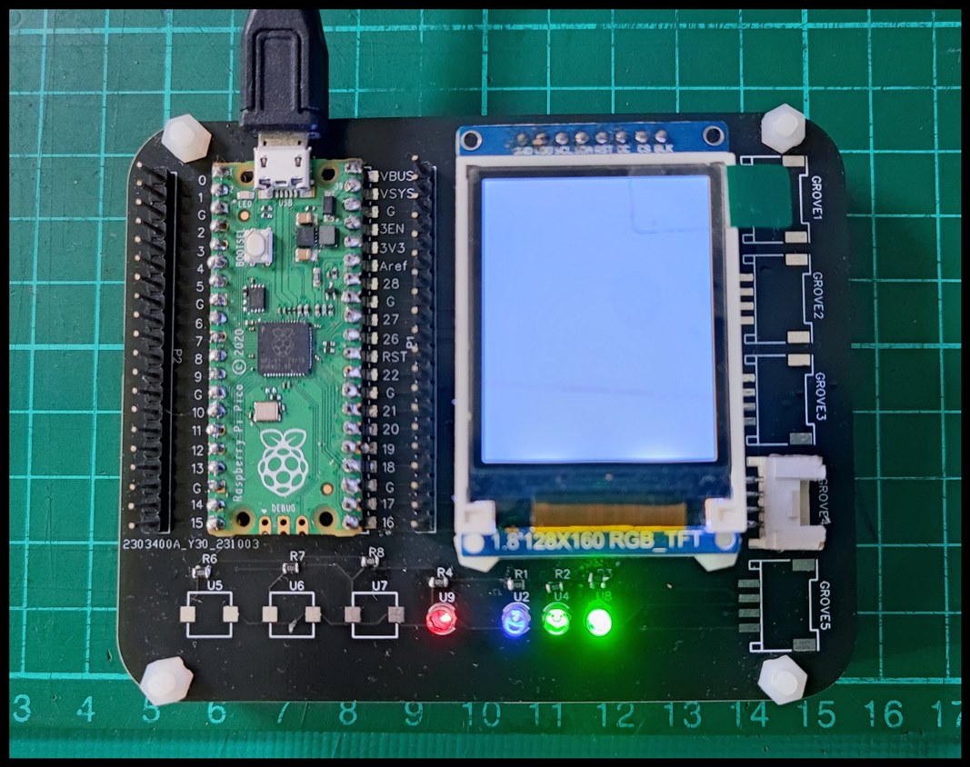
For the hardware part, obviously, I am using the Raspberry Pi Pico. On top of that, since I am building an automated plant watering system, I will be using the soil moisture sensor to get the soil moisture value and the relay to control the water pump. Since the beginning of the project, I have been excited about having a specific board that can be used as an interface for this project. Hence I decided to build one. The figure below shows the image of the board.

image

image

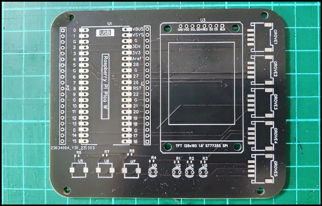
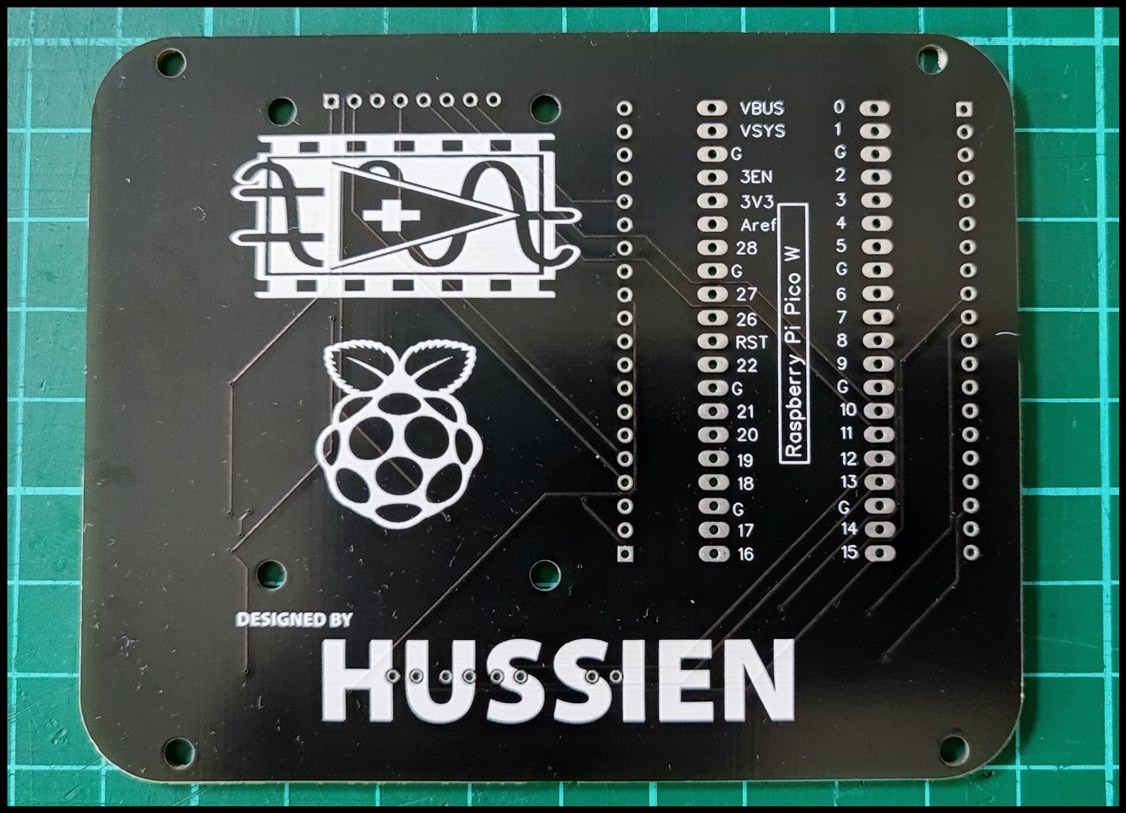
This board basically has a TFT 1.8" display, 4 grove ports, 3 indicator LEDs and 3 push buttons. Unfortunately, later I came to know the pin output does not tally with the SCPI lab tool. However, I am still able to access the other pin through the pin header. The image below shows the component populated on the PCB board. As can be seen in the figure below, some of the components are still missing. This is because I am yet to receive it. Expressionless

image

As for the soil moisture sensor, I have decided to use the Maker Soil Moisture Sensor from Cytron Technologies. Below is the image of the sensor.

imageimage

image

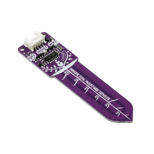
This sensor measures soil moisture by capacitance sensing, where the presence of water in the soil will increase the probe capacitance. The output of the sensor is analog output; higher moisture levels will produce a lower output voltage. Moreover, it comes with an LED indicator for easier indication of the moisture level.

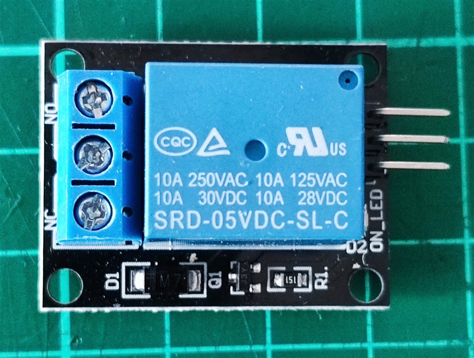
The next component which I used was the relay module. The purpose of the relay module is to turn ON and OFF the submersible water pump. Since the water pump requires a higher voltage, the relay will act as an automatic switch for the submersible water pump. Below is the image of the relay module, as well as the water pump.

image

image

Software Development

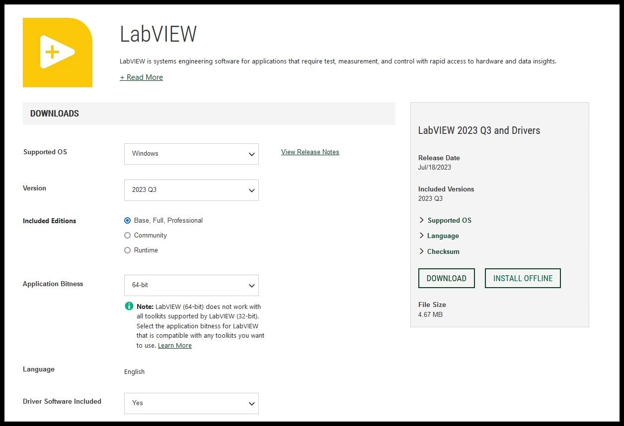
For the software development, we will be using the LabVIEW. First, need to download the LabVIEW Community Software. The installation process is pretty straightforward. Just follow the steps and you are done with setting up the software. Below is the screenshot of the download window, whereby we need to choose the OS and other things before we can start to download the software. Just be sure to select the community editions.

image

Once it is installed, the next step is to download the SCPI tool. I came to know about the SCPI tool from lesson 10. The SCPI tool is used for communication with Raspberry Pi Pico and LabVIEW. Thanks to Shabaz and Jan Cumps. Also in the same GitHub, there are example files included. I downloaded the file and tried to run it. Below are the videos of the test which I have done.

You don't have permission to edit metadata of this video.
Edit media
x
image
Upload Preview
image

Example Digital Out.

The video below shows the test for digital out.

You don't have permission to edit metadata of this video.
Edit media
x
image
Upload Preview
image

From the video above, I am able to control the LED connected to pin GP15 which is at PIN2. Refer to the screenshot of the reference below.

image

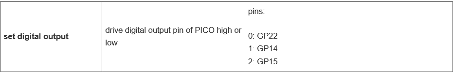
I am only able to use the GP15, since the GP22 and GP14 is either not connected or connected to other peripherals. The next example that i would like to try is the analog input example.

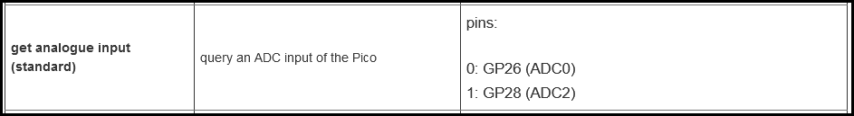
Example Analog Input.

The video below shows the test for analog input.

You don't have permission to edit metadata of this video.
Edit media
x
image
Upload Preview
image

For the analog input, I am using the GP26 which is connected to Pins 0. From the video above it can be seen that the value of the moisture sensor is updated accordingly in the LabView as the moisture level of the soil changes from dry to wet.

image

Auto Plant Watering System

 Now we have seen that both the digital output and the analog input are working fine as per the example. Now we will start to design the "Auto Plant Watering System".

Firstly all the components or devices are connected.

image

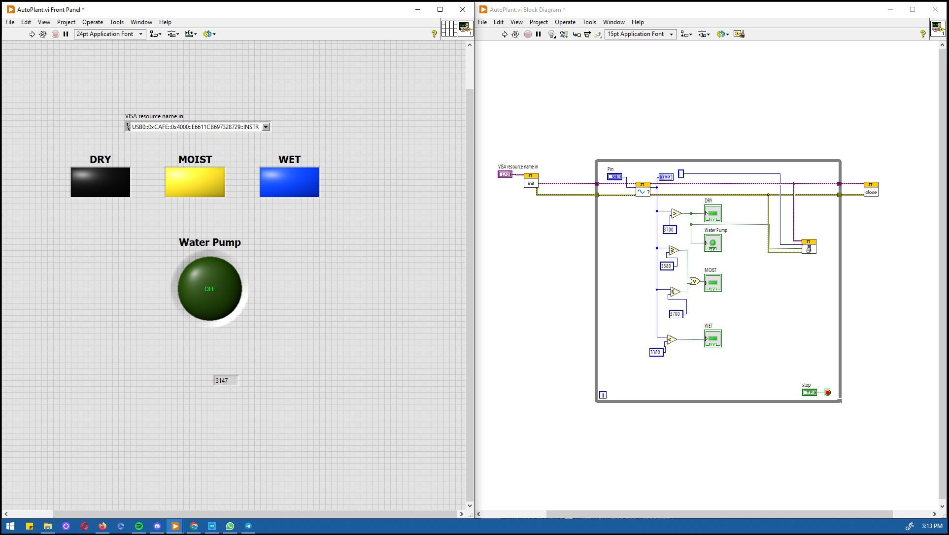
Next, we designed the Auto Plant front panel and continued with the block diagram.

image

System Testing And Deployment

Now we are ready to test the system. Basically how it operates is that the water pump is activated if the soil becomes dry and the pump will stop once the soil becomes wet. The video below is a demonstration of the system.

You don't have permission to edit metadata of this video.
Edit media
x
image
Upload Preview
image

And this the test video

You don't have permission to edit metadata of this video.
Edit media
x
image
Upload Preview
image

Results

As a result, I would say that the objective of the project is achieved. The plant watering is automated using the Raspberry Pi Pico and LabView(of course by using other peripherals as well). Saying that a lot more cosmetic work can be done to make the project more easily deployed. Also, the PCB board which I designed for this project can be updated, to cater or to incorporate the pinouts as per the SCPI pins layout. In the future I would like to add more features to this project, specifically to add water reservoir monitoring as well as the humidity and temperature sensor.

Conclusion

In conclusion, I would say this design challenge was very interesting from the very beginning. Starting the quiz which indirectly teaches the user to get familiar with the LabView environment. Moving on with building the project was quite a challenge though( especially for me who had zero experience on using LabView before). Overall it was a very good experience.

TIPS & TRICKS

One tip that I can share is, to always refer to the help if there are any doubts or unclear of any of the functions in the LabView. Personally, I refer mostly to the HELP window to solve the error which I face.

  • Sign in to reply
  • meera_hussien
    meera_hussien over 1 year ago in reply to Jan Cumps

    Thanks again Jan Cumps . This is very helpful.

    • Cancel
    • Vote Up 0 Vote Down
    • Sign in to reply
    • More
    • Cancel
  • Jan Cumps
    Jan Cumps over 1 year ago in reply to meera_hussien

     scottiebabe made an overview of the currently used pins.

    In the source code, each module has a header and c file. If you want to extend a module, check how the pins are assigned, counted, and initialised . Add/remove the pin(s) you want.

    If that pin is already used by another module, remove it, and decrease that module's  count if needed.

    The GPIO in, out, and the ADC use an array to hold the pins. Adding / removing pins is done by changing the array. Initialisation and counting functions will adapt to that.

    When you (have to) change a pin in the PWM module, you have to study a bit to understand how it works. The Pico PWM api isn't as straightforward.

    Board LED and i2c_0 pins are reserved.

    • Cancel
    • Vote Up 0 Vote Down
    • Sign in to reply
    • More
    • Cancel
  • meera_hussien
    meera_hussien over 1 year ago in reply to Jan Cumps

    Thanks Jan Cumps . Good to know that. Is there any reference or resources on how this can be done?

    • Cancel
    • Vote Up 0 Vote Down
    • Sign in to reply
    • More
    • Cancel
  • meera_hussien
    meera_hussien over 1 year ago in reply to DAB

    Thanks DAB 

    • Cancel
    • Vote Up 0 Vote Down
    • Sign in to reply
    • More
    • Cancel
  • meera_hussien
    meera_hussien over 1 year ago in reply to Andrew J

    Thanks Andrew J 

    • Cancel
    • Vote Up 0 Vote Down
    • Sign in to reply
    • More
    • Cancel
>
element14 Community

element14 is the first online community specifically for engineers. Connect with your peers and get expert answers to your questions.

  • Members
  • Learn
  • Technologies
  • Challenges & Projects
  • Products
  • Store
  • About Us
  • Feedback & Support
  • FAQs
  • Terms of Use
  • Privacy Policy
  • Legal and Copyright Notices
  • Sitemap
  • Cookies

An Avnet Company © 2025 Premier Farnell Limited. All Rights Reserved.

Premier Farnell Ltd, registered in England and Wales (no 00876412), registered office: Farnell House, Forge Lane, Leeds LS12 2NE.

ICP 备案号 10220084.

Follow element14

  • X
  • Facebook
  • linkedin
  • YouTube