With the glitz of Hollywood and the studios of Burbank California, it may be hard to believe that some parts of Los Angeles County are located in a rural area where there is no piped-in gas or water. Such is the case where I live on the edge of the Santa Clarita Valley. Here, we use Propane, and our water magically comes from an underground aquifer, 350 feet below the surface. Having no water bill is great! But, one bears the responsibility to our community to use water wisely as this is NOT an unlimited supply. In the least, wasting water can reduce the pool neighbors rely upon for the care of livestock and growing crops. In my area, corn, wine grapes, and alfalfa are common. Worst case, depleting an aquifer can cause it to collapse internally, thus destroying its ability to supply water at all. This was the dreaded fear of the California drought these last five years.

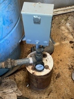
-The "Magic Well"

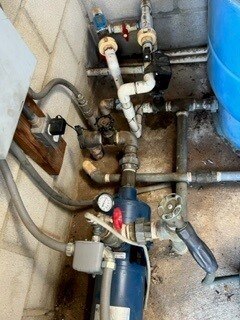
-A common well & boost pump system with a pressure tank. Having an automatic shut-off valve on the outlet would be quite valuable.
As you can see, making sure water is not wasted is of critical importance, and unlike in the city, where lot sizes are small and broken water pipes are easily discovered, when miles of pipes, sun-beaten automated irrigation equipment and frozen cracked pipes are involved, breaks happen frequently, and the losses can be very expensive. Because a well can supply only so much water over a day’s time, a supply tank, or cistern is employed to maintain a high volume of water for immediate use. This becomes especially useful during fire season when large volumes come in handy to our firefighters. This is also a fire code requirement. My particular system holds 32,000 gallons and if emptied as a result of a break, a cost of $3000 is realized that week as several trucks deliver makeup water. I have had my tanks drop several times and I have often felt the need to design a monitoring and control system.
My design employs a Raspberry Pi Pico programed with National Instruments LabVIEW. In brief, the main loop in the Pico continuously monitors two elements GP8 as an input which monitors gross flow. Using a paddle type flow switch comprised of a paddle inside of a 2” pipe that is coupled to a switch on top of the device with a water-tight seal, a gross leak causes the paddle to move froward and actuate the switch above it. Along with a small capacitor to reduce debouncing somewhat and a pull-down resistor, Input GP8 receives an input High. This change of state starts a timer that counts to 1 hour and when one hour elapses, a shutdown sequence commences. Outputs: GP2 and GP7 are activated, go high, closing off the automated water source valve with a 10 second long pulse AND turning on a visual/audible alarm with a sustained High. A Wi-Fi connected alert module can be activated off that output; if desired.
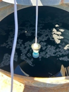
Likewise, if a smaller leak prevails and there is no gross flow, but rather a small flow that drops the tank level sufficiently, an adjustable float switch is engaged when an internal reed switch senses the dropped float and turns input GP10 High. Unlike GPO8, which has a long delay, GP10 has only a 1-minute delay before it calls the same shutdown sequence. The LabVIEW VI would compare the elapsed time and "reset" to zero if the condition did not exceed the maximum time value.

- The tank level float switch.
As a bonus, the valve controller can have state switches that indicate full-open or full-closed. These can use the Pico’s 3.3V supply to set inputs GP4 & GP5 high and in-turn flip high outputs: GP18 & GP19 which have LED indicators on them. This can be handy when diagnosing problems. On a reset, a power down of the Pico and the automatic action of the valve, when the reset button is pressed, gets us back to a normal operation state, ready to wonderfully save a well.
LabVIEW code is straightforward involving one main while loop that continuously monitors and engagements that trigger For loops to enable control outputs at the desired time interval. Time counted in the For Loop that does not exceed the set, maximum value (via comparison), loops back a reset to zero, when the condition is corrected. While for the purposes of this competition and its sponsors, a "driving computer" is required and several portable Windows computers can be safely placed into a humid well room environment, a more economical approach would be to adapt the code and save it on the device itself to which there is ample information on how to do that online. Then the Pi Pico would boot and run without a host PC much like an Arduino running on compiled code from an Arduino compatible compiler, like the one from Aledyne engineering. Again, this is outside of the scope of this exercise, but a great consideration as having a computer running in a control room is not as cheap as the Pi Pico itself.
Future versions with a wider scope at well and water system health, can control an H-Bridge circuit from two Pi Pico outputs that can reset the valve state automatically, using variables in LabVIEW to hold the states. Third-party security hardware can be exploited to monitor more parameters like current and temperature. Let’s say a pump is failing; temperature would show a rise over time. Excessive current consumption is another characteristic to monitor. Water filter status can be monitored by installing pressure transducers on the inlet and outlet. A rising differential would indicate a dirty filter. Telemetry can be ported using LabVIEW data sockets and other tools to get data to a smartphone and ping a user. The possibilities are endless.

