Hello!
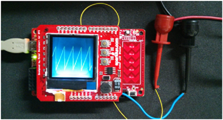
This example utilizes the analog and digital components of PSoC 4 to implement an oscilloscope. The oscilloscope supports software voltage scaling, time scaling, and measuring signal parameters. The oscilloscope supports input signals of amplitude 0-3.3V and signal frequencies of up to 20KHz.
Note: There was a minor change to the download file made on 5/17/2013 to include more comments on the design and code.
Forum Post Attachments:
At the bottom of this post we are including the following items:
- Example Project Zip File
- Zip File of Images
- Project Schematic
- Component Configurations
Components Used:
The user can download the example project at the bottom of this post. The project uses the following list of Creator Components:
- SPI Master
- PWM
- ADC SAR Sequencer
- CyPin
- CyClock
Note this example does not use the GLCD component detailed in element14 examples #009-011.
The components are configured by right clicking on the component in your Top Design schematic view and selecting Configure. Please enable the following selections in the Configuration windows for the listed components above.
Firmware Description:
The main.c firmware is included in the example project. Please review the commented sections for more details. A brief description of the project is given below.
The SAR ADC of the PSoC 4 is used to sample the input signal and store the digital values in a buffer. Out of these sampled values, 128 samples are selected starting with a value greater than average of the collected samples. The selected samples are then displayed on the Color LCD.
The three buttons available on the Color LCD shield are used for voltage scaling, time scaling and to display the signal parameters (Vp-p and frequency).
Button S1 is used for voltage scaling. On every button press, the scaling value is incremented and the collected samples are suitably scaled before they are displayed on the Color LCD.
Button S2 is used for time scaling. On every button press, the period of PWM is varied which changes the sampling frequency of the SAR ADC.
Button S3 is used to display the parameters of the signals (Vp-p and the frequency). On every button press, the minimum and the maximum value of the samples as well their positions are found and used to calculate the Vp-p and the frequency of the signal. This is a crude method implemented to calculate the signal parameters and accurate values cannot be expected.
Hardware Connections:
Please connect the Sparkfun Graphics LCD Shield to the Pioneer Kit.
To read in an analog value insert a wire into A5 or P2[5]. This pin is the outside pin on the ‘Analog In’ header of the GLCD shield or J2 header on the Pioneer Board. The user will need to also make sure to tie the ground of what they are testing to the ground of the Pioneer board.
Test Your Project:
Once the kit is programmed with the example project the user will be able to connect an input to the Shield and being to use the oscilloscope.
I hope this example can help you out in your design.
Best,
Matt

