element14 Community
element14 Community
    Register Log In
  • Site
  • Search
  • Log In Register
  • Members
    Members
    • Benefits of Membership
    • Achievement Levels
    • Members Area
    • Personal Blogs
    • Feedback and Support
    • What's New on element14
  • Learn
    Learn
    • Learning Center
    • eBooks
    • STEM Academy
    • Webinars, Training and Events
    • More
  • Technologies
    Technologies
    • 3D Printing
    • FPGA
    • Industrial Automation
    • Internet of Things
    • Power & Energy
    • Sensors
    • More
  • Challenges & Projects
    Challenges & Projects
    • Design Challenges
    • element14 presents
    • Project14
    • Arduino Projects
    • Raspberry Pi Projects
    • More
  • Products
    Products
    • Arduino
    • Dev Tools
    • Manufacturers
    • Raspberry Pi
    • RoadTests & Reviews
    • Avnet Boards Community
    • More
  • Store
    Store
    • Visit Your Store
    • Choose Another Store
      • Europe
      •  Austria (German)
      •  Belgium (Dutch, French)
      •  Bulgaria (Bulgarian)
      •  Czech Republic (Czech)
      •  Denmark (Danish)
      •  Estonia (Estonian)
      •  Finland (Finnish)
      •  France (French)
      •  Germany (German)
      •  Hungary (Hungarian)
      •  Ireland
      •  Israel
      •  Italy (Italian)
      •  Latvia (Latvian)
      •  
      •  Lithuania (Lithuanian)
      •  Netherlands (Dutch)
      •  Norway (Norwegian)
      •  Poland (Polish)
      •  Portugal (Portuguese)
      •  Romania (Romanian)
      •  Russia (Russian)
      •  Slovakia (Slovak)
      •  Slovenia (Slovenian)
      •  Spain (Spanish)
      •  Sweden (Swedish)
      •  Switzerland(German, French)
      •  Turkey (Turkish)
      •  United Kingdom
      • Asia Pacific
      •  Australia
      •  China
      •  Hong Kong
      •  India
      •  Korea (Korean)
      •  Malaysia
      •  New Zealand
      •  Philippines
      •  Singapore
      •  Taiwan
      •  Thailand (Thai)
      • Americas
      •  Brazil (Portuguese)
      •  Canada
      •  Mexico (Spanish)
      •  United States
      Can't find the country/region you're looking for? Visit our export site or find a local distributor.
  • Translate
  • Profile
Cypress Kits
  • Products
  • Dev Tools
  • Cypress Kits
  • More
  • Cancel
Cypress Kits
Forum PSoC 4 Pioneer Kit Community Project#035 – UART, I2C, and SPI Joystick Example
  • Blog
  • Forum
  • Documents
  • Members
  • Mentions
  • Sub-Groups
  • Tags
  • More
  • Cancel
  • New
Cypress Kits requires membership for participation - click to join
Actions
  • Share
  • More
  • Cancel
Forum Thread Details
  • Replies 20 replies
  • Subscribers 18 subscribers
  • Views 967 views
  • Users 0 members are here
  • 100projects
Related

PSoC 4 Pioneer Kit Community Project#035 – UART, I2C, and SPI Joystick Example

cy.wbz
cy.wbz over 9 years ago

Hello!


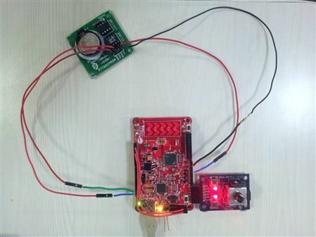
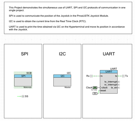
This Project demonstrates the simultaneous use of UART, SPI and I2C protocols of communication in one single project. SPI is used to communicate the position of the Joystick in the Pmod JSTK Joystick Module. The I2C is used to obtain the current time from the Real Time Clock (RTC). UART is used to print the time obtained via I2C on the Hyperterminal and move its position in accordance with the Joystick.
  • PSoC 4 Pioneer Kit
  • PmodJSTK – 2 Axis joystick
  • Real Time Clock DS1307


Forum Post Attachments:


At the bottom of this post we are including the following items:

  • Example Project Zip File
  • Zip File of Images
    • Project Schematic
    • Component Configurations


Components Used:


The user can download the example project at the bottom of this post. The project uses the following list of Creator Components:

  • SPI
  • I2C
  • UART
  • CyPins
  • CyClock


The components are configured by right clicking on the component in your Top Design schematic view and selecting Configure. Please enable the following selections in the Configuration windows for the listed components above.


Firmware Description:


The main.c firmware is included in the example project. Please review the commented sections for more details.


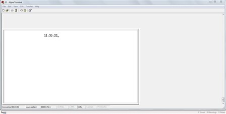
This firmware example is an excellent demonstration of how the PSoC 4 can interface using three different serial interfaces (SPI, I2C, and UART). The example reads in the time data from the RTC using I2C, then pulls the positioning data from the Joystick using the SPI interface, and then completes the example by sending the RTC value to hyperterminal and using the joystick to control where the RTC value is displayed on the screen.


While the example almost seems like a game, please step back and consider how this type of system dynamic would be common in an end design. We can imagine pulling in data from two separate inputs and having to relay those values up to a main host or PC. In many case the input data may affect other data and require some type of data manipulation.


Hardware Connections:


The user will need to populate and solder the 6 pin Pmod header to the Pioneer kit. This header will allow the user to connect the Pmod Joystick module. The SPI interface that reads the values from the joystick will be configured and set in the PSoC 4 project. There is already a physical connection between the Pmod module and the PSoC 4 device. The SPI pins on the PSoC 4 will be: P3[0], P3[1], P3[5], P0[6], and P0[7].


Next connect the Pioneer board to the Real Time Clock board. First connect the Vdd and GND lines from the Pioneer kit to the Clock board. Next connect your I2C lines from the Pioneer board to the Clock board. The I2C lines are: P4[0] and P4[1].


Also connect the PSoC 4 UART connections to the PSoC 5LP device so the UART positioning can be relayed up to the host.


PSoC 4 P3[7] -> P5LP P12[6]

PSoC 4 P0[5] -> P5LP P12[7]


Test Your Project:


After connecting your project please program the example into the PSoC 4 device. Once programmed then launch your Hyperterminal software to view the UART data traffic. Then use the joystick to control the output on the hyperterminal software.


I hope this example can help you in your design.


Best,

Matt

Attachments:
I2C_SPI_UART.cyprj.Archive01.zip
0447.Project Images.zip
  • Reply
  • Cancel
  • Cancel

Top Replies

  • Former Member
    Former Member over 9 years ago in reply to jesusantoniocar +1

    Hello Jesus,

    There are two types of SPI component available for the PSoC 4 in the PSoC Creator

    1) UDB based

    2) SCB based


    For providing the external clock to the UDB based SPI, open the Advanced tab in the…

  • jesusantoniocar
    jesusantoniocar over 9 years ago in reply to jesusantoniocar +1

    Hi.

    It is an interesting article to share:


    PSoC 4 Chained Clocks


    http://www.cypress.com/?rID=81829&source=home_cdc


    best regards,


    Jesus Antonio

  • icemanfiveoh
    icemanfiveoh over 8 years ago in reply to icemanfiveoh +1

    Hi,


    I was successfully able to get the terminal to display the DS1307 RTC Time but it is all over the terminal window. I am going to see if i can strip away some code to stop that from happening. Also,…

  • icemanfiveoh
    icemanfiveoh over 8 years ago in reply to icemanfiveoh

    Hi,


    I was successfully able to get the terminal to display the DS1307 RTC Time but it is all over the terminal window. I am going to see if i can strip away some code to stop that from happening. Also, the next step is to see if i can start implementing my previous Arduino project into the PSOC4. I hope so.


    Jason

    • Cancel
    • Up +1 Down
    • Reply
    • Cancel
  • dandumit
    dandumit over 8 years ago

    Hello,

    I have tried for hours to set  CY8CKIT-042CY8CKIT-042 to use SPI Master on Digilent port P3.5 P3.0 P3.1 and P0.6
    I have found your project and it looks that you have mapped SS to 0.7 and after that you have added another separate pin SS and you are managing it separately from code.


    Could you please give me some more details on this specific work around ?


    Kind Regards,

    DAniel

    • Cancel
    • Up 0 Down
    • Reply
    • Cancel
  • Former Member
    Former Member over 8 years ago in reply to dandumit

    Hello Daniel,


    The design uses an (Serial Communication Block) SCB based fixed function SPI Master. The SCB mandates usage of specific pins for MISO, MOSI, SCLK, and Slave Select. Also, the line (Slave Select 1) SS1 can be used only if line (Slave Select 0) SS0 is used. This means that, the design has to connect P0.7 as the slave select for the project to build successfully.


    The design will work fine with a stand-alone PSoC 4, but in PSoC 4 Pioneer Kit (CY8CKIT-042) this pin is connected to the user switch*. Also, the pin P0.7 is not available on any of the headers. This is why another pin is used in design to implement Slave Select.


    One other way to do this without using an extra pin is to use a USB based SPI Master component from PSoC Creator instead of SCB based SPI Master.


    *Note: The pin P0.7 is also used to wakeup the device from low power modes such as Sleep, Deep-Sleep, Hibernate, and Stop. This is the reason for using P0.7 for switch.


    Hope this helps.


    Happy Programming!


    Ranjith

    • Cancel
    • Up 0 Down
    • Reply
    • Cancel
  • Former Member
    Former Member over 7 years ago in reply to Former Member

    Hello Friend


    Can you get me your contact detail. I have lots of queries regarding SPI in PSoC 4.


    Kindly get me reply as soon as possible.


    Thnak you.


    Bharat Surani

    suranibharat4@gmail.com

    • Cancel
    • Up 0 Down
    • Reply
    • Cancel
  • Former Member
    Former Member over 6 years ago in reply to icemanfiveoh

    HIII icemanfiveoh,


    You Have solved the RTC issue That is outputting a wierd value 00:00:80, i am getting same value 00:00:80 on hyperterminal, can you please me what is the issue .........i am using same example with psoc 4 controller but getting 00:00:80  on hyperterminla......please uplode code if any one solved this issue


    • Cancel
    • Up 0 Down
    • Reply
    • Cancel
  • jimyu
    jimyu over 5 years ago in reply to Former Member

    Dear Rohit Warule,


    Were you able to get the time to display using the above code example.


    I am not able to display the correct time......I only get 00:00:00 or 00:00:80 on hyper-terminal.


    Please help.

    • Cancel
    • Up 0 Down
    • Reply
    • Cancel
  • koudelad
    koudelad over 5 years ago in reply to jimyu

    Hello,

    the latest post in this a year and a half old, while the original article is 4 years old.


    I would suggest the following steps:

    1) Upgrade the project to the newest components (newer versions of PSoC Creator and the hardware component libraries were released).

    2) Try to verify whether you really get the clock data from the RTC.

    3) If the PSoC doesn't work as expected, try to debug it to the part where you succesfully read the RTC registers.

    4) In case of troubles, zip the whole project and create a new question / discussion here, add as much details as possible (schematics, RTC register values...).


    David

    • Cancel
    • Up 0 Down
    • Reply
    • Cancel
  • jimyu
    jimyu over 5 years ago in reply to koudelad

    Dear David,


    I spoke with the Cypress guys and they are working on this with me.....any help from the people here would be great.

    • Cancel
    • Up 0 Down
    • Reply
    • Cancel
  • arshtab45
    arshtab45 over 4 years ago

    Hi,


    I am new to PSoC and trying to understand it one bit a time. I need help in a project I am working on in which I intend to serially transmit data using NTX0 ,NRX0 (Radiometrix)RF transmitter and receiver modules respectively. I am using two PSoC 4 kits . I have made hardware connections with one PSoC4 kit and NTX0 and other PSoC 4 kit to NRX0 module.


    Components used:


    PSoC Kit:


    CY8CKIT-042CY8CKIT-042PSoC 4 Pioneer Kit


    RF module:

    NTX0-27.095-4(Transmitter)

    NRX0-27.095-4 (Receiver)


    I have some doubts which I was hoping could get cleared here at the community;


    1. What are the blocks I should use in the schematics?(I am using ADC and UART  at TX end, and only UART at the Receiving end)

    2. How to configure the pins in PSoC creator at the transmitting end and at the receiving end?

    3. How to program the receiver (PSoC  4) to receive the data from the other kit(TX)?

    4. How to show this communication using PuTTy?


    Awaiting response.


    Thank you,

    Arshiya Tabassum

    • Cancel
    • Up 0 Down
    • Reply
    • Cancel
  • koudelad
    koudelad over 4 years ago in reply to arshtab45

    Hello,


    Have a look at the PSoC 101 videos, there are great tutorials:

    http://www.cypress.com/video-library/PSoC/psoc-101-lesson-12-uart/387666


    David

    • Cancel
    • Up 0 Down
    • Reply
    • Cancel
<
Element14

element14 is the first online community specifically for engineers. Connect with your peers and get expert answers to your questions.

  • Members
  • Learn
  • Technologies
  • Challenges & Projects
  • Products
  • Store
  • About Us
  • Feedback & Support
  • FAQs
  • Terms of Use
  • Privacy Policy
  • Legal and Copyright Notices
  • Sitemap
  • Cookies

An Avnet Company © 2022 Premier Farnell Limited. All Rights Reserved.

Premier Farnell Ltd, registered in England and Wales (no 00876412), registered office: Farnell House, Forge Lane, Leeds LS12 2NE.

ICP 备案号 10220084.

Follow element14

  • Facebook
  • Twitter
  • linkedin
  • YouTube