


Hello!
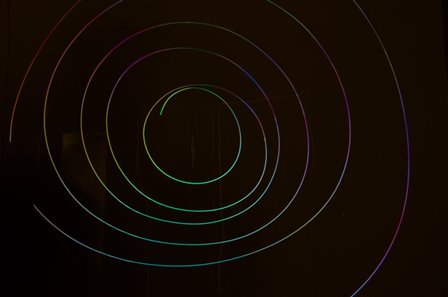
We took yesterday off due to the US holiday. The 4th of July US holiday is typically characterized by fireworks in the night sky. Today our example will show you how to create your own fireworks in the night’s sky using the RGB LED. In this example uses a sparkfun 3 axis accelerometer and the PSoC 4 Pioneer kit. We use the accelerometer and the movement of the Pioneer kit to change the colors on the RGB LED.

This project uses our new Component Pack 6 release of PSoC Creator 2.2 SP1. Please take a look at our earlier post on this new release:
Forum Post Attachments:
At the bottom of this post we are including the following items:
- Example Project Zip File
- Zip File of Images
- Project Schematic
- Component Configurations
Components Used:
The user can download the example project at the bottom of this post. The project uses the following list of Creator Components:
- PWM
- UART
- I2C
- CyClock
- CyPin
The components are configured by right clicking on the component in your Top Design schematic view and selecting Configure. Please enable the following selections in the Configuration windows for the listed components above.
Firmware Description:
The main.c firmware is included in the example project. Please review the commented sections for more details.
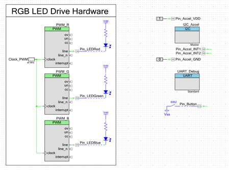
In the example we are communicating to the accelerometer via an I2C interface. This interface will report the positioning on the three axis. This value is then translated into color values on the RGB LED. We use the LED RGB source files used in some of our earlier examples, like example #019. These files give us easy API access to the RGB LED. Make sure you copy those files into your example.
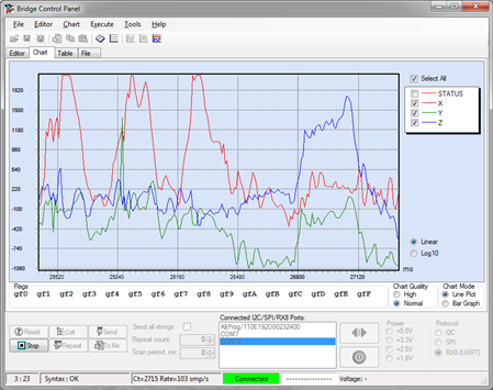
We then report the 3 axis positioning over the UART bridge so it can be reported up to the Bridge Control Panel. We are able to chart our positioning in real time using the chart features. You can use the following Bridge Control Panel command to read out the values from the PSoC 5LP USB-UART bridge:
RX8 [h=43] @STATUS @1X @0X @1Y @0Y @1Z @0Z
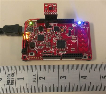
Hardware Connections:
You will need to solder on a male connector to the sparkfun 3 axis accelerometer. The header will be connected into the Pioneer board Arduino headers. Connect the accelerometer into header J3 using Pins 1-6. Ground should be pin 1. Please be very careful when plugging this in as you might reverse the polarity on the power and ground connections and hurt your accelerometer. Please see the below image for the correct orientation.
Test Your Project:
Connect the 3 axis accelerometer board to the Pioneer kit. Program the kit and begin waving the kit around to see the RGB LED change. If you are interested in creating similar long exposure photos using a DSLR camera, take a look at the following video.
I hope this example can help you in your design.
Best,
Matt


