


Hello!
Today’s example was talked about in the we released earlier this week. We are going to use Processing to generate an image on a 16x32 RGB LED matrix board. We use a Processing GUI to load the desired image onto the PSoC 4 device to display on the LED Matrix board.
Forum Post Attachments:
At the bottom of this post we are including the following items:
- Example Project Zip File
- Processing Example
- Zip File of Images
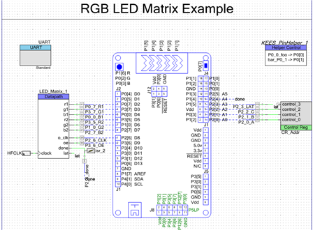
- Project Schematic
- Component Configurations
Components Used:
The user can download the example project at the bottom of this post. The project uses the following list of Creator Components:
- UART
- LED Matrix Datapath Component (custom)
- Control Register
- Annotated Component for the Pioneer Board (custom)
- Pin Helper Component (custom)
- CyClock
- CyPin
- ISR
Firmware Description:
The main.c firmware is included in the example project. Please review the commented sections for more details.
In this example we provide a new custom component to drive and control the LED Matrix. This component was implemented on the UDBs of the PSoC 4 to handle the timing-sensitive sensitive and tedious portions of the designs. You will see the ‘LED Matrix’ component in the example. This component .h and .c files are included in the project. This component supports the following APIs to write to the PSoC 4:
void DrawPixel(uint8 x, uint8 y, RGB c, color *matrix)
void ClearPixel(uint8 x, uint8 y, color *matrix)
void ClearScreen(color *matrix)
In this example we are receiving data over the PSoC 5LP USB-UART bridge from the PC Processing application. We then take that data and display it out on the LED Matrix Panel. This project supports a 5-bit color image at a refresh rate of 360 Hz.
Here is a rough flow of the project when in operation:
- The Component clocks out 32 RGB values to the 2 planes of the panel.
- It then latches the data, enables the LED driver, and triggers a ‘done’ signal.
- An ISR fires on the ‘done’ signal, and this increments the row, writes new RGB data to the Component (FIFOs) from a buffer, and handles the Binary Code Modulation (BCM) for color control
- In main code, the buffer for the image to be drawn on the panel is modified (when necessary). This is done when the UART sends new data to be drawn. Previous 3 steps go on endlessly.
The other half of this example uses the Processing IDE to generate an application that transmits the ICON image down to the Pioneer board. The code for the Processing example is provided below.
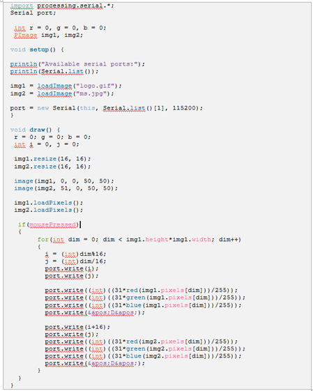
You will need to ensure that the Processing application is selecting the correct COM port created by your computer for the Pioneer USB-UART capabilities. Also you will need to enter in the correct image in your script.
You will see in the images for the kit example that we have put some paper over the LED Matrix. This is due to the brightness of the LEDs. When you are working on the example it’s easier to save your eyes to put a little diffuser over the LEDs when testing.
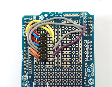
Hardware Connections:
In this example we use an Arduino Breadboard shield to perform all of the wiring between the LED Matrix board and the Pioneer kit. In this example we use an RGB LED Matrix Panel from Adafruit to generate all of our images. The panel is a 16x32 RGB LED panel that uses a serial addressing scheme to light up the LEDs.
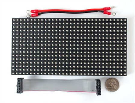
Adafruit supplies a tutorial page on the LED matrix panel. We suggest you reviewing this page to see how the panel works and how to interface the panel to the PSoC.
The Adafruit web site has a tutorial on connecting and wiring up the panel to an Arduino kit. You can follow the same instructions to connect the panel to the Pioneer board.
The above header can be summarized in the following table:
Pin name | Description |
R1, G1, B1 | R, G, B value for a pixel in plane 1 |
R2, G2, B2 | R, G, B value for a pixel in plane 1 |
A, B, C | 3-bit row address |
OE | Output Enable (active low) |
LAT | Latch (active low) |
CLK | Clock |
GND (4 pins) | Ground |
The panel can be thought of as 2 ‘planes’, each with 8 rows. The RGB color in the 8 rows of plane 1 are controlled using (R1, G1, B1) and likewise for plane 2. The 8 rows are addressed using the (A, B, C) lines. Columns are accessed by clocking out values (serial interface of sorts); i.e. after one clock you are at column 1, after 31 clocks, you are at column 31.
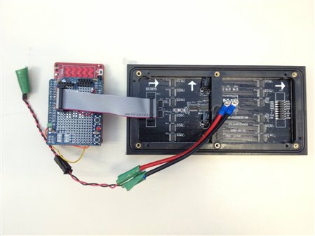
We also connect the UART pins between the PSoC 4 and the PSoC 5LP device to enable the USB-UART bridge capabilities. Connect two wires between the Pioneer Arduino headers and the PSoC 5LP headers.
PSoC 4 P4[1] -> P5LP P12[6]
PSoC 4 P4[0] -> P5LP P12[7]
Test Your Project:
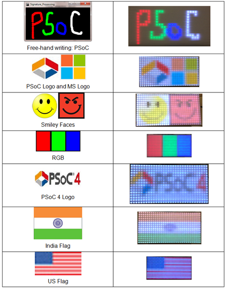
Connect your hardware and program the Pioneer kit with the target firmware. Start up the Processing script and load in your image. Download that image to the Pioneer board for display on the LED Matrix board. The following image is a set of the logs images and their output on the LED Matrix.
I hope this example can help you in your design.
Best,
Matt

