Hello!
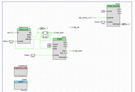
In today’s example we are exploring more motor connections. This project leverages the Pmod hardware ecosystem. We use a simple H-Bridge to control the motor. We use a human input through the CapSense slider to determine motor speed and direction, while using the Timer Counter component to calculate the RPMs of the motor and display that out via the UART.
Forum Post Attachments:
At the bottom of this post we are including the following items:
- Example Project Zip File
- Zip File of Images
- Project Schematic
- Component Configurations
Components Used:
The user can download the example project at the bottom of this post. The project uses the following list of Creator Components:
- CapSense
- UART
- PWM
- Timer Counter
- CyTFF
- Debouncer
- CyClock
- CyPins
Firmware Description:
The main.c firmware is included in the example project. Please review the commented sections for more details.
In this example we showcase a good mix of both firmware and hardware design. The project implements code to handle the CapSense, UART, and RPM calculations. In some of our past examples we have seen examples implementing CapSense and UART controls providing easy inputs and ouputs for users.
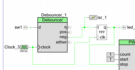
The key to today’s example continues with the theme we’ve been stressing for the last few weeks, which are the hardware only design elements. In this example we see that the system logic has been pulled into the hardware removing unnecessary firmware. In this example we are using a Toggle Flip Flop to take in the button selections and driving an LED and starting the PWM for the motor. In this example we do not need to write any code for this control, instead we have implemented the logic in hardware.
Hardware Connections:
For this example you will need to connect the Digilent Pmod module to the J5 header.
You will need to connect the UART connections from the PSoC 4 pins P0[4] and P0[5] to the PSoC 5LP header P12[6] and P12[7].
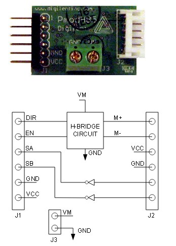
Connect the PSoC 4 pin P3[5] to the Pmod DIR pin.
Connect the PSoC 4 pin P3[0] to the enable line of the Pmod header.
Connect the PSoC 4 pin P3[1] to the SA pin of the Pmod header.
Connect power and ground.
Connect the motor to the M+ and M- pins of the Pmod header. Power and Ground will be needed to power the motor.
The following image was included in the Digilent Pmod datasheet.
Test Your Project:
Program the Pioneer board with the example code. Then turn on the motor by pressing the SW2 button. Then select the motor speed and direction by moving your finger along the CapSense slider. Launch a hyperterminal program to see the output and speed of the motor.
I hope this example can help you in your design.
Best,
Matt


