


Hello!
In yesterday’s example we show cased the Figaro TSG 5042 carbon monoxide gas sensor. When that example was first created there was an initial task of simulating the gas sensor to ensure that our design would interface correctly. It is common when you are in the lab or maker space to not have access to your external hardware, but there may be a need to unit test your design. In this example we are going to talk about how we simulated the sensor and validated our hardware design before we hooked up the sensor.
Forum Post Attachments:
At the bottom of this post we are including the following items:
- Example Project Zip File
- Project Images
- Gas Sensor Datasheet
- Excelsheet with data
Components Used:
The user can download the example project at the bottom of this post. The project uses the following list of Creator Components:
- Opamp (x2)
- SAR ADC
- UART
- CyPins
Firmware Description:
The main.c firmware is included in the example project. Please review the commented sections for more details.
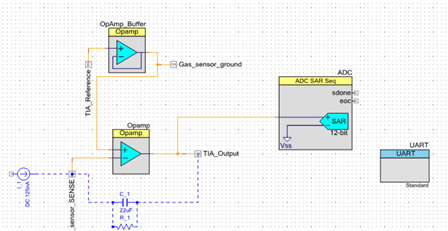
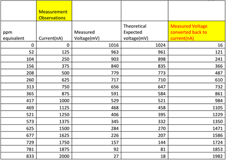
For this example we had access to a power supply that allowed us to step up the current supplied to the PSoC. We used this supply as an input to our system. We then took data based on the values measured. Those values can be displayed on the UART output on a hyperterminal window for data collection.
For this example we used the same firmware written for the previous example but attached our current supply to the sensor input.
Once we had the sensor in hand we were able to measure the various values based on carbon monoxide values. We see that they correlated very closely to the theoretical values we collected with our test system.
Hardware Connections:
You will need to connect a couple of items for this example. First you will need to connect the bypass resistor (R1 503k ohms) and capacitor (C1 22uF).
Next connect the UART P4.1 pin to the P12.6 pin on the PSoC 5LP header.
Test Your Project:
Connect the hardware to the Pioneer board including capacitor, resistor and sensor. Next connect the UART bridge to the PSoC 4 board. Launch the hyperterminal software to view the data received from the Pioneer board. Adjust your current supply to view data over a range of supply values.
I hope this example can help you in your design.
Best,
Matt
| 5042pdf.pdf | |

