


Hello!
In today’s example we are examining the comparator component and creating a simple example using the Pioneer board. In the example you will use a wire to connect one of two inputs to the comparator to a 5V source. By connecting one of two pins to the voltage we will either turn on or turn off an LED. The output state of the comparator will be displayed over the UART to a hyperterminal application.
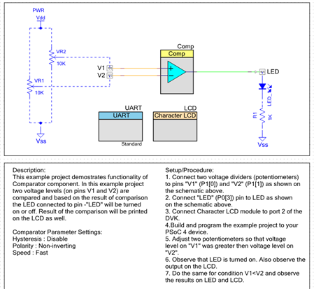
In the schematic below the user is given drawing to connect two potentiometers. This is not necessary to examine the functionality of the comparator. To see how to use the comparator we will need only a loose wire.
Forum Post Attachments:
At the bottom of this post we are including the following items:
- Example Project Zip File
- Project Images
Components Used:
The user can download the example project at the bottom of this post. The project uses the following list of Creator Components:
- Comparator
- LCD
- UART
- CyPins
Firmware Description:
The main.c firmware is included in the example project. Please review the commented sections for more details.
In this example we are using a simple wire to trigger high conditions on the two inputs for the comparator. In the schematic layout of the project we include external annotated components in the design. These annotated components are external potentiometers. You would be able to breadboard up this setup if you have the available hardware. In the example we used a simple wire to trigger the high state. In a real world example you may have variable voltage inputs that vary over time.
We include two components, UART and the LCD. In this example you can target the CY8CKit-038 and CY8CKit-001 that include an LCD module. In this example we wanted to use the Pioneer board so we enabled the UART bridge. The LCD code is commented out and can be added if needed.
Hardware Connections:
For this example the user will need to connect GPS module to the UART component outputs.
We must connect P4.1 and P4.0 to the PSoC 5LP header P12.6 and P12.7 to enabled the UART bridge on the PSoC 5LP
We will also connect a wire to the 5V source on the Arduino headers. We will then connect this wire into one of the two input sources for the PSoC 4 device. This will force one of the two inputs to be higher than the other thus enabling the component output.
Test Your Project:
Program the example into the Pioneer board. Launch the hyperterminal application to display the comparator output. Take a wire and trigger one of the two inputs using the 5V source on the Arduino headers. See that the output changes depending on which input you connect.
I hope this example can help you in your design.
Best,
Matt
| Comp_P4_v1_0.pdf | |


