


Hello!
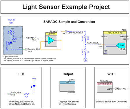
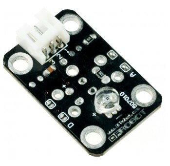
In today’s example project we will create a light sensor project that interfaces with the DFRobot Ambient Light Sensor (DFR0026). This example project uses an opamp interfaces to an ADC SAR to read in the value from the light sensor. The value from the light sensor is then transmitted over UART over the PSoC 5LP USB-UART bridge and displayed on the PC.
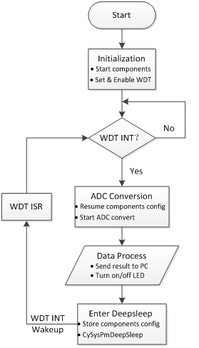
The key point of this example is that the PSoC 4 is put into a deep sleep mode and uses the Watch Dog Timer (WDT) to trigger an interrupt to sample the ADC and then move back into deep sleep mode. This is a common solution needed for devices that are power conscience or power limited.
Forum Post Attachments:
At the bottom of this post we are including the following items:
- Example Project Zip File
- Project Images
Components Used:
The user can download the example project at the bottom of this post. The project uses the following list of Creator Components:
- OpAmp
- ADC SAR Seq
- UART
- WDT
- CyPins
Firmware Description:
The main.c firmware is included in the example project. Please review the commented sections for more details.
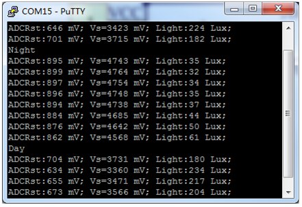
In this project the PSoC 4 device enters deepsleep mode after processing and transmitting the light sensor data. To reduce the power usage of the example we control the ground of the light sensor with a pin on the PSoC 4. Before entering deepsleep, the light sensor ground pin is set to high to disable the sensor. After wakeup, the pin is set to low, to enable the light sensor for ADC conversion. Once the device has powered the light sensor the SAR ADC samples and coverts the output voltage of the light sensor. The PSoC 4 then transmits the result to Hyperterminal via the UART and the PSoC 5LP bridge. The PSoC 4 then identifies if it is night or day through a range detection. The device then enters deepsleep to be awoken by the WDT on the next interrupt.
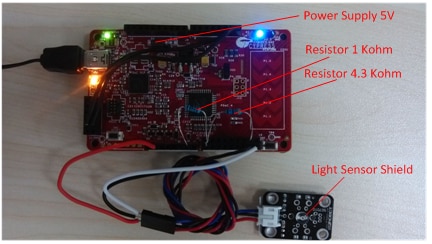
Hardware Connections:
This example project utilizes a number of external components that are details in the PSoC 4 schematic design. Additionally users will need to connect the light sensor to the specified connections.
The UART lines from the PSoC 4 must be connected to the PSoC 5LP UART bridge (P12.6 and P12.7).

Test Your Project:
Connect the hardware and then program this example project into the Pioneer board. Connect the Pioneer board to the PC and then launch the hyperterminal to view the output from the example.
I hope this example can help you in your design.
Best,
Matt


