


Hello!
In today’s example we are continuing to expand on the earlier projects detailed in example and . In this project we are showcasing a solution typically needed for System Management Controllers (SMC). System Management is typically seen in server solutions where a Microcontroller is needed to manage the system and backplane data flow. This Microcontroller is not handling data transfer into or out of the servers, but maintaining the system ensuring that the servers continue to run as designed. The critical aspects of the server center around thermal management (temperature measurement, fan control, power supervision) as well as monitoring that the server system are property functioning.
When trying to target specific designs with customers we will often look to showcase the unique characteristics of the PSoC focusing on configurable nature of the digital and analog peripherals. Many times for end users they are able to incorporate onboard functionality into the PSoC, saving board space and build costs. We saw this earlier this week with our .
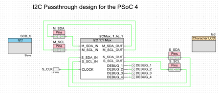
In today's example we identified disparate functions common in the system management solution and worked to integrate that functionality into the PSoC to save costs to the customer and decrease board space while increasing the design’s robustness. This example showcases the 1:1 input I2C mux, or Smart Wire. In applications where the Power Supervisor is the only I2C node on the board, it is trivial to integrate the 1:1 mux to a single internal I2C slave block. For customers who require true redundancy, instantiating two independent I2C slave blocks in PSoC provides an even more robust solution.
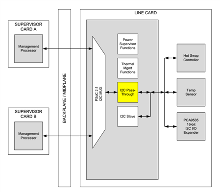
In reality, however, a typical server card can have 30 to 40 I2C nodes on it, supported through a combination of I2C muxes and repeaters. For PSoC to be successful at integrating at the server front end, we will require the ability to have a pass-through for the I2C traffic coming from the supervisor cards. In the following block diagram we show where the I2C pass through fits in the system design. Instead of requiring the Management Processor to hanlde the system management we outsource that to the PSoC. Here the PSoC can report a variety of data back to numerous Management Processors.
Forum Post Attachments:
At the bottom of this post we are including the following items:
- Example Project Zip File
- Project Images
Components Used:
The user can download the example project at the bottom of this post. The project uses the following list of Creator Components:
- LCD
- I2C (slave)
- CyPins
- I2C mux 1:1
- ISR
Firmware Description:
The main.c firmware is included in the example project. Please review the commented sections for more details.
This example showcases how a PSoC was used to pull unique system functionality into the configurable digital peripherals. This allowed for more functionality to be brought into the PSoC removing excess components and reducing BOM costs. This was achieved by understanding the system need and creating a custom component to handle the use cases. We see in the schematic design that most of the functionality was achieved in hardware without the need for extensive firmware work. Most of the component implementation is captured in the verilog file associated with the component. You can view this file by navigating to the ‘Component’ tab in the workspace explorer. Once there you can open the .v file to view the source.
Naturally for this solution we can add additional components to the design, such as an ADC for thermal management, another PWM to control LEDs for a fan, and additional analog features.
Hardware Connections:
There is no hardware for this solution. This example delivers a new custom component.
Test Your Project:
This example is a showcase of an end solution. There is no hardware for this example.
I hope this example can help you in your design.
Best,
Matt