


Hello!
In today’s example we are showcasing a PSoC 4 battery charging and monitoring example. Very often in an end product you will need to have the ability to monitor your battery voltage and assess the state of the hardware’s power system.
In this example we utilize the liquidware Lithium Battery Pack Shield as our charging and monitoring source. The Lithium Power Pack example is composed of two parts: charting and battery monitoring. The Charging part of the project has the PSoC 4 enter a hibernate mode and wake up when the battery voltage drops below the reference voltage. The second half o the example supports a battery monitory that checks the battery voltage every 30 seconds and will let the user know to charge the battery when it is low.
Forum Post Attachments:
At the bottom of this post we are including the following items:
- Example Project Zip File
- Project Images
Components Used:
The user can download the example project at the bottom of this post. The project uses the following list of Creator Components:
- OpAmp
- SAR
- Timer
- LCD
- Comparator
- CyPins
- CyClock
- ISR
Firmware Description:
The main.c firmware is included in the example project. Please review the commented sections for more details.
The firmware and the schematic design are divided into two halves, the charging mode and the battery monitoring mode.
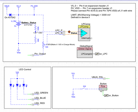
The charging mode utilizes the PSoC 4 comparator to wake up the PSoC 4 device when charging is completed. In this design we give an external reference voltage to the Comparator. To reduce power consumption, we set the output pin to low in charging mode and high in battery monitoring mode.
The LEDs show different program statuses. A button can be also used to wake up the PSoC 4 device to judge if charging is available.
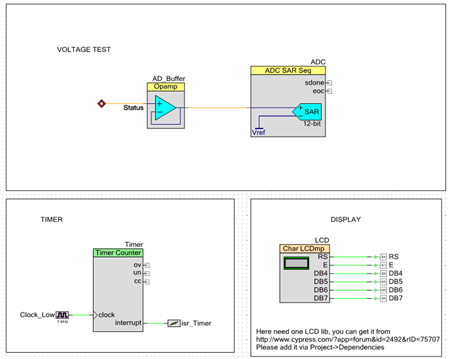
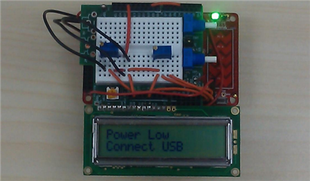
The battery monitoring mode utilizes the SARADC and the OpAmp as a buffer which is used for battery voltage monitoring. A timer triggers an interrupt every 30 seconds. When the interrupt is triggered the monitory status is displayed on the LCD.
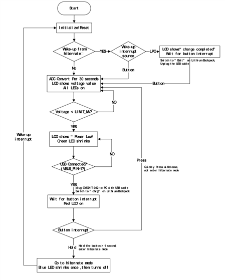
The following image provides you a detailed flow chart for the example code. It may be helpful when designing your application to develop flow charts before writing code. A flow chart will help to divide up elements of your design and provide a way to isolate areas to perform testing to ensure proper functionality.
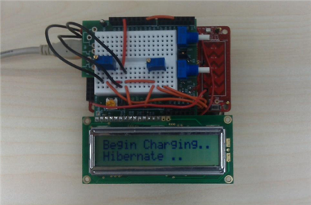
Hardware Connections:
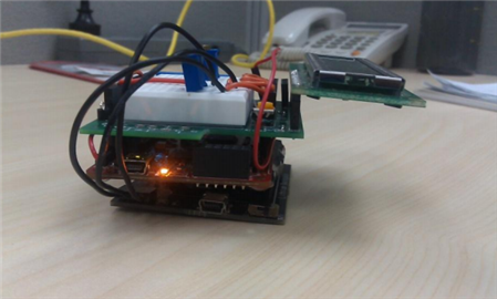
Please connect the Lithium Battery Pack to the Pioneer Kit. In this example we also used a breadboard mounted on top of the Lithium Battery to wire up resistors and an LCD. You can use any breadboard shield. In this example we are using an internally developed shield. For information on the resistor network please take a look at the schematic design as the external resistors are detailed there. These resistors can be laid out on the breadboard.

Test Your Project:
Program your example and begin to charge and discharge your battery system. View the output on the LCD screen.
I hope this example can help you in your design.
Best,
Matt
