


Hello!
In the example released today we will show the user how to create the simplest of USB projects. In this example we will be using the USB-HID driver provided across OS platforms. In this example we will take the example in project #4 (linked below) and expand to incorporate a GUI that reads data and controls features on the kit. In this example we have provided example code for GUIs running on Windows, Mac, and Linux machines. In the images below we show the windows based GUI.
For more information take a moment to review the earlier posts:
Forum Post Attachments:
At the bottom of this post we are including the following items:
- Example Project Zip File
- Project Images
User Modules Used:
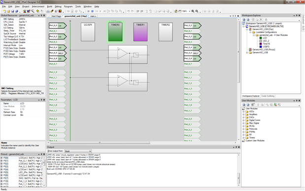
The user can download the example project at the bottom of this post. The project uses the following list of Creator Components:
- USBFS
- LCD
- LED
- Timer16
Firmware Description:
The main.c firmware is included in the example project. Please review the commented sections for more details.
In this example we have created a simple USB device, using the HID driver, that can be used to shuttle generic data base and forth between a computer and the PSoC over the USB drive.
In the example we define two data buffers for the USB communication, one for the data inputs and outputs. The data is processed in two separate functions, Process_EP1() and Process_EP2(). The Process_ES1() function includes the value read from the timer and the current status of the push button connected to SW2. The function updates the data buffer and is continuously called from the main function. The Process_ES2 function reads the user’s inputs into the GUI window and updates both the LED state and PWM Duty Cycle value.
Hardware Connections:
There are no hardware configurations for this example. All of the onboard connections have been made. The user will need to connect the PSoC 1 USB connector to the host computer after programming the device.
Test Your Project:
Build the project and program the PSoC 1 device using the program button in PSoC Designer, Program>Program Part. Once the device has been programmed change the USB connection to the PSoC 1 USB connector.
Once the device has connected launch the GUI application. The GUI will both read from and write to the device on the kit.
For entering in data the user will be able to set the PWM Duty Cycle and apply that value to the device. This value is displayed on the LCD module on the kit. You will see that the LCD module is updated after pressing the ‘Update’ button.
<html><head><title>Jive SBS</title></head>
<body><font face="arial,helvetica,sans-serif">
<b>Error</b><br><font size="-1">
An general error occurred while processing your request.
</font></font></body></html>
The next feature is the checkbox for the ‘LED’. You can select and deselect the checkbox and see that the LED is turned on and off.
The item in the GUI is a text box that reads a timer value from the device. This value is put into the text box. The text box is labeled as an ADC, but since the kit does not have a POT we have output the timer value to this field instead. We provide example code in the project to change the output to a different value.
Finally there is an LED switch status that toggles between ‘OFF’ and ‘ON’ when the user presses the SW2 button on the kit.
<html><head><title>Jive SBS</title></head>
<body><font face="arial,helvetica,sans-serif">
<b>Error</b><br><font size="-1">
An general error occurred while processing your request.
</font></font></body></html>
These inputs and output in the GUI are examples to users to create their own custom applications targeting the CY8C24x93 devices. All of the source code, for each OS, is included below as well as a link to the USB application note that will help users better understand USB.
I hope this example can help you in your design.
Best,
Matt
| AN82072_001-82072.pdf | |
