


Introduction
Magnifiers and other visual inspection tools are essential with working with small electronics. This blog post does a quick round-up of several low-cost ways to achieve this for hobbyists, and shows how to assemble a digital video microscope using the Gizmo 2 single board computerGizmo 2 single board computer (SBC). See video below!:
The topic of PCB inspection magnifiers and cameras has come up many times on Element 14 forums. This blog post shows my experiences so far.
Motivation
When working with protoboard and stripboard often the work can be done with the naked eye. This is not always the case when working with modern tiny surface mount components. Basically, they are very small!

The pins can be separated by 0.4mm or less, component markings are just as small, and flux deposits make it hard to view any detail until the board is immaculate.
Handheld Magnifiers
I often make do with a small handheld magnifier with a built-in lamp and it works ok for the larger SMD devices. I have tried many different types of handheld magnifiers in the past.
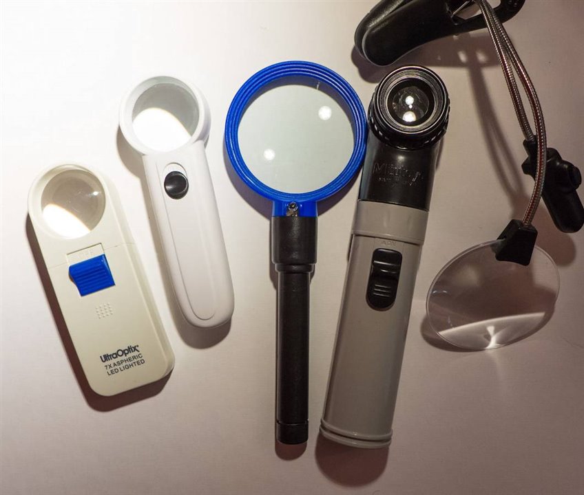
Usually the magnification is quite low, so one is forced to use it close-up to the eyes in order to get a bit more magnification. Possibly this is not healthy! My favorite is the one on the left in the photo (incidentally amongst the cheapest, under $10). It has an LED on the underside and it is angled just right to be very useful. The batteries last a very long time – I’ve not had to change them for a couple of years.
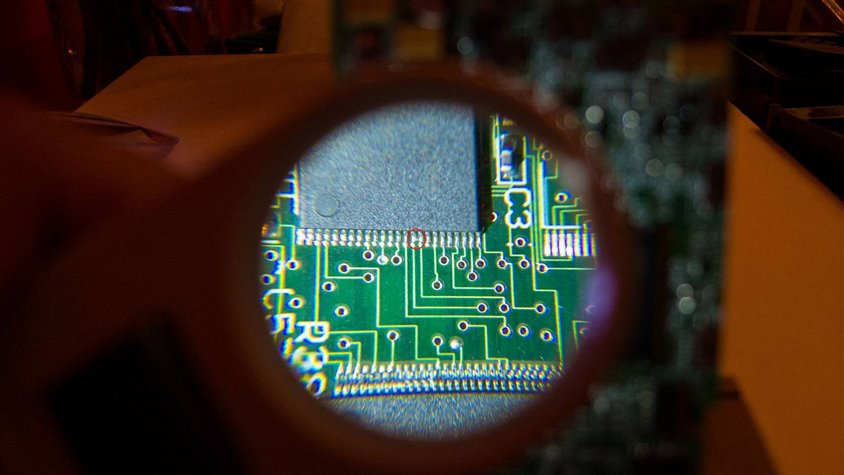
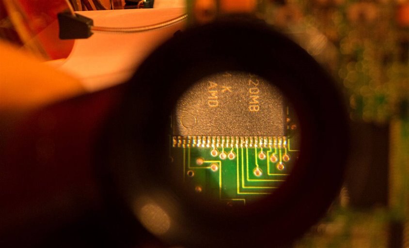
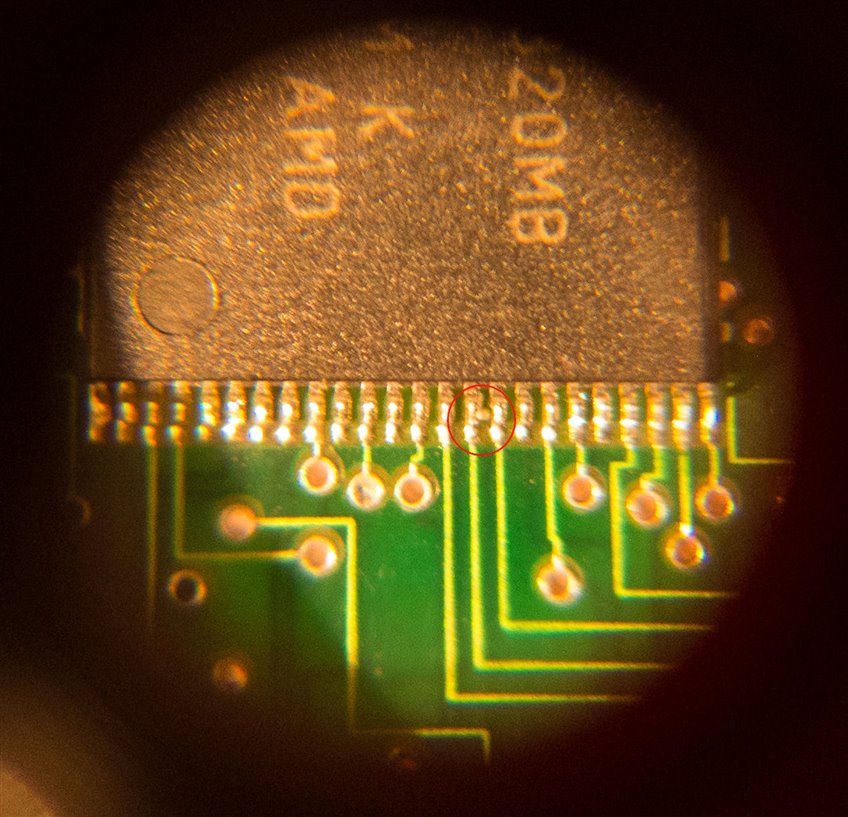
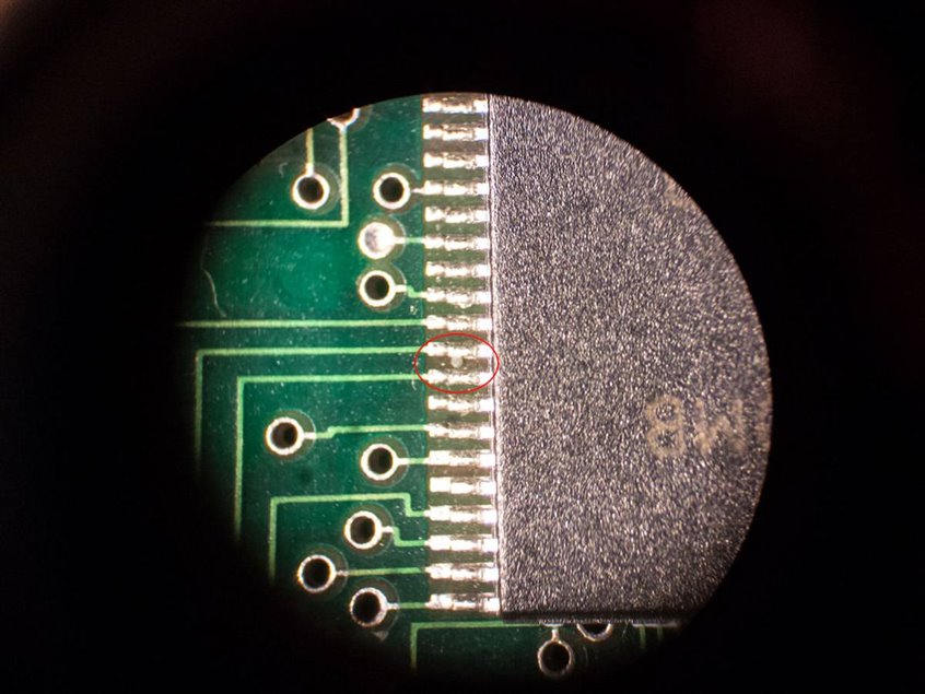
Here is an example PCB with what looks like a fault, as seen through this magnifier. I’ve tried to take the photograph to reflect what I see through the magnifier with the naked eye. So, I’ve positioned the camera very close (about 5cm away) from the magnifier, and it has been manually focussed to a relatively short distance which is what I would do to try and get more magnification out of it. The red circle shows the fault – something like a blob of solder bridging two pins of a 0.5mm pitch integrated circuit. It can be clearly seen, although with a bit of eye strain. I think this is a good magnifier, provided your eyesight is not bad.
Looking at the next magnifier from the left, the photo below is the view through the super-cheap e-bay special (just a few $). It has two LEDs on the underside, but they have poor color rendering as you can see from the photo, which makes it quite hard to get a clear view of things. I would suggest that this is second-worst magnifier in the lineup (the worst is yet to come).
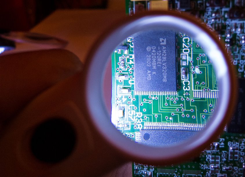
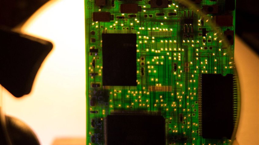
The photo below shows the view from a SAAME magnifierSAAME magnifier - the middle magnifier in the lineup photo.
It is a physically larger diameter magnifier, and the result while clear, shows that the magnifier is not intended for detailed PCB inspection. Also, there is an incandescent bulb fitted in the handle (the type of bulb that was popular in flashlights – it has a glass molded lens as part of the bulb), but it doesn’t illuminate the correct area very well. The photo below shows the PCB being illuminated from the rear, just to get a clearer view.
Another approach is to use an inspection loupe type of magnifier, which is designed for close-up work. One from Mitutoyo was used for the photograph below. It comes in two parts – the Mitutoyo handle with an incandescent bulbMitutoyo handle with an incandescent bulb and the Mitutoyo magnifier portionMitutoyo magnifier portion .
In use it has to be placed almost against the PCB, and then your eye can be anything from around 10cm to right up against the loupe, and the target will remain at a good level of magnification. The solder blob is clearly visible. Also, notice how the PCB on the right of the photo is blurred, yet on the left side of the photo all the stuff on the table is still in focus. This is because the Mitutoyo loupe is less straining on the eyes. Plus the level of magnification is the highest out of all the ones tested. It is a really great choice.
The solder blob is clearly visible with the Mitutoyo loupe as can be seen in this close-up photo:
Finally, the worst magnifier was one from a local store; it was intended for use as a clip-on book lamp; it was on sale and so I thought it was worth a try. However nothing was too clear through it! and I learnt that a book magnifier is almost useless for electronics work.
Point-and-Shoot Cameras
If your point-and-shoot camera has ‘macro’ capability then chances are that it can be useful to some degree for PCB inspection. A small tripod and good lighting can be useful, and the aperture turned down slightly to gain some depth of field. I got reasonable results with a point-and-shoot camera. The only problem is that most compact cameras that have some HDMI capability will not display a live view via HDMI; the HDMI capability is usually only for viewing photos and recordings. Therefore a photo can be taken of the PCB and then inspected either on the built-in display or from an attached PC or via HDMI as a static image or recording.
Low cost USB Cameras
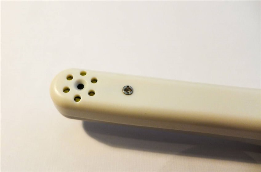
I’ve also experimented in the past with so-called “dental inspection cameras” available from ebay at very low cost (so not the same quality as the cameras used by real dentists I hope!). They are electric-toothbrush-sized and have a sideways pointing camera surrounded by white LEDs:
They have a USB interface. There is not really a lot inside them:
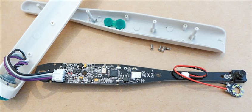
These supposed “dental inspection cameras” are easy to use and do not need any focussing because they have a relatively large depth of field. Unfortunately it is at the expense of picture quality. The reason is because the device has a very restricted aperture (i.e. a small pinhole) to get the depth of field, but the sensor is tiny and so the side effect is that the very low light level will result in a noisy image unless the PCB is flooded heavily with light. The built-in LEDs around the camera are not great; better to use an external lamp that can be aimed from an adjustable angle. Another issue is that the video image is compressed and doesn’t look great. In summary the dental USB camera approach to PCB inspection is barely usable.
Lab Microscopes and Machine Vision Cameras or DSLRs
A binocular microscope is another option. This one was a very old model Meiji EMT that I got for next to nothing and cleaned up:
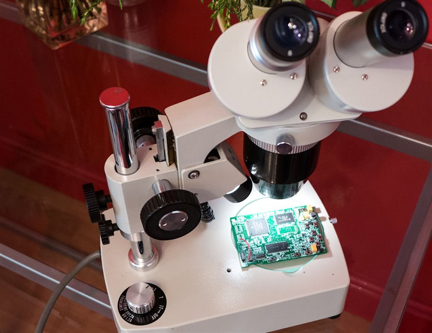
If you are buying a microscope for PCB inspection, you’ll need to check that you can get a good distance between the object to be observed and the lens assembly – otherwise larger components like electrolytic capacitors may get in the way when trying to read the markings on a small surface mount integrated circuit. This Meiji microscope allows for about 8cm working distance. It also has a built-in lamp with angle adjust capability so that the subject under test can be illuminated from the best direction for maximum contrast. The image is excellent and it is very easy to observe detail, this is the view looking down the eyepiece (10x magnification eyepiece, 2x magnification objective):
The Meiji EMT has a 4x objective setting too if even greater magnification is needed. Microscopes can be connected to a camera with an appropriate adapter. If a digital single lens reflex (DSLR) camera is available then the lens mount is standards-based so there is a strong possibility that an adapter could be purchased. Otherwise it is sometimes possible to build your own adapter.
Yet another approach with a DSLR is to just purchase a macro lens. The results will be extremely good.
Many DSLRs have a ‘live view’ capability via USB, so that the output can be observed on a PC.
I didn’t want to dedicate a DSLR for PCB inspection so I decided to use an industrial camera (used for things like machine vision, e.g. inspection of items on a conveyer belt in a factory). They are compact cube-shaped things, around the size of pool cue chalk. Often the lens is bigger than the camera.
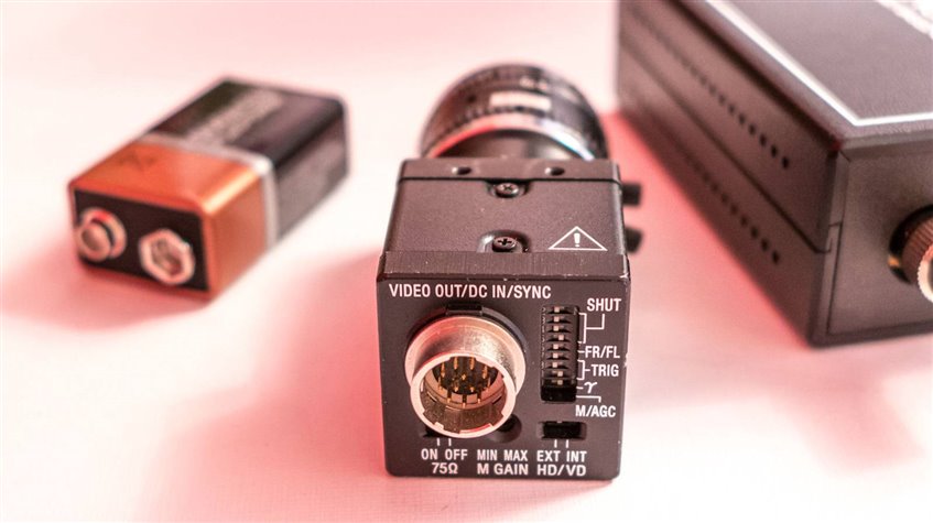
This is the view of the sensor (not recommended to leave it open like this, in case dust gets inside!):
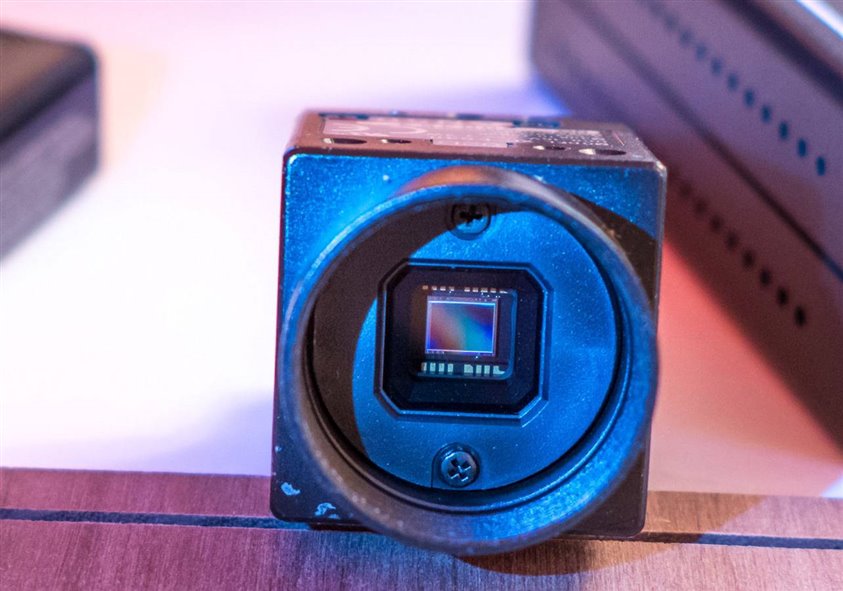
These cameras come with C-mount or CS-mount fittings which are standards that define the screw thead and diameter and the distance from the mount to the sensor so that lenses can be interchanged between cameras. It was easy to find an off-the-shelf adapter to connect between the C-mount camera and the microscope from ebay. The particular camera in the photo above is standard definition (and used and monochrome – I don’t think it would be worth spending money on a color standard definition camera nowadays – see below for HD cameras) and has an analog (composite) output that can be directly connected to a monitor so that I don’t have to use a PC for it. Otherwise it is possible to connect to a PC for recording images or video by using a video capture card.
Using GigE Vision Cameras
The binocular microscope is good, but I still wanted something more convenient to use directly from the work bench. There are fancy microscope stands, but I didn’t want to spend that kind of money on an experiment. Besides, I felt the binocular microscope was overkill for home use.
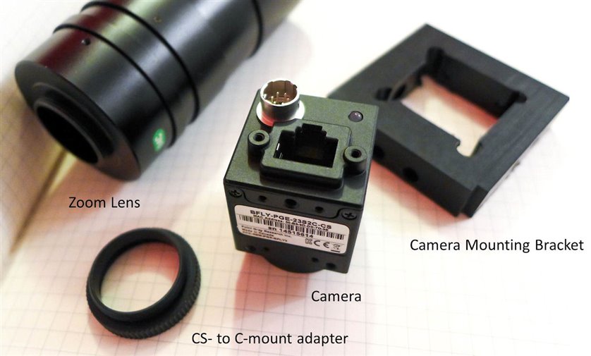
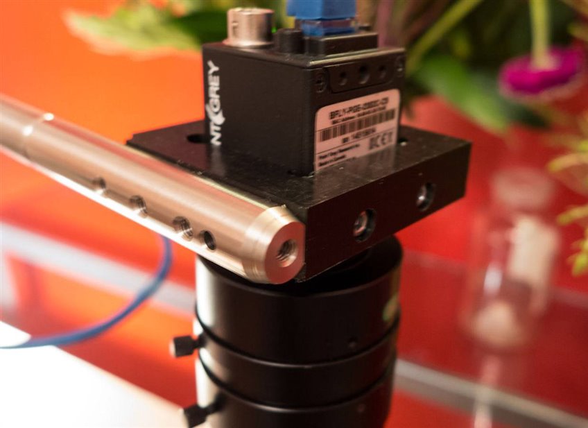
So, after further research I obtained a Point Grey camera from ClearView Imaging. I selected this camera because of the good sensor size and sensitivity. It is physically quite small and cube-shaped – about 3cm on each edge:
The camera uses a Sony IMX136LQJ sensor (PDF overview) which is quite large (1/2.8” format, 6.4mm diagonal so it will work well with lenses intended for 1/3” and 1/2" format sensors) and has up to 12-bit resolution for very good quality video. It is of reasonable price and it has full HD resolution at 27fps (ideal for video recording) and a Gigabit Ethernet interface for raw uncompressed video capability. With uncompressed HD quality at a good frame rate (more than 25fps) more than 80Mbytes/sec of data needs to be transferred so USB 2.0 is out the window, and Gigabit Ethernet becomes a highly attractive option.
Machine vision/inspection cameras with a Gigabit Ethernet interface usually support a standard known as GigE Vision that allows them to interoperate with software from other vendors. They are also referred to as GigE cameras if they comply to the GigE Vision specification. For briefness I will refer to the physical interface as a GigEth interface.
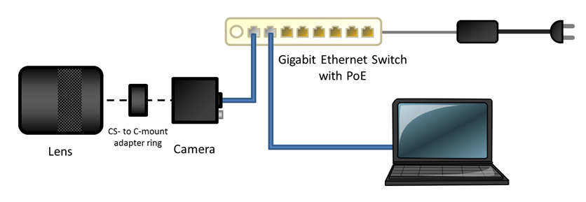
For the lens I went with a recommendation on a forum and selected a Computar zoom lens model MLH-10X. The zoom capability is extremely useful. Fixed focal length alternatives include Fujinon (Fujifilm) lenses – they have very nice fixed focal length lenses intended for machine vision. An adapter to go from CS- to C-mount is also needed, because the Point Grey camera has a CS-mount and many machine vision lenses have a C-mount.
My reason to go for a zoom lens is that it is highly desirable to go from a zoomed-out view on a PCB and then quickly drill-down to a smaller area by adjusting the zoom. Also, with machine vision lenses it is possible to quickly lock the aperture and focus settings with a thumbscrew, and a benefit of this was found to be that you can adjust the zoom by feeling for the lens and only one ring will turn (the zoom ring) without taking your eyes off the PCB.
For instant results the camera can be directly connected to a PC with a GigEth interface and the camera is powered up with an external power supply.
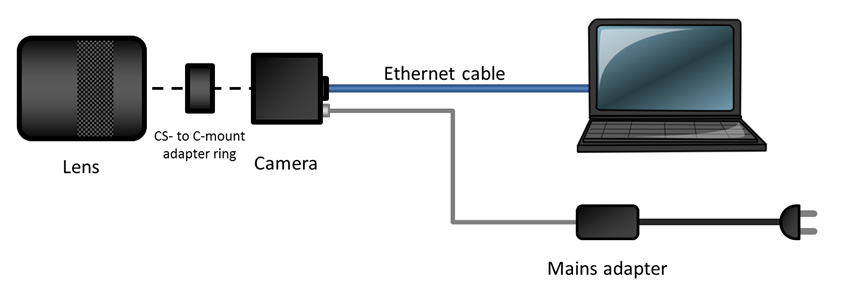
Note that Microsoft Windows can auto-assign the network interface an IP address and so will the camera; thus no DHCP nor static IP addressing is needed; if you test with Mac or Linux, do share the procedure in the comments below.
The image quality was good. The Computar lens is positioned 15cm or much further away from the PCB so it won’t interfere with large components on the board or other items on the work bench. Good to strong lighting is still needed for a noise-free image but the camera is still usable with general home lighting and no task lighting switched on. With the aperture wide open the depth of field is still actually not bad – improves as the aperture is reduced at the expense of more noise of course.
Building a Camera Stand
Some type of stand is required; with a zoomed-in picture the camera would be unusable without one. The camera has M2 and M3 screw holes so a piece of plastic was drilled appropriately (or a 3D printer could be used). The photo below shows the bits and pieces used to construct the camera head.
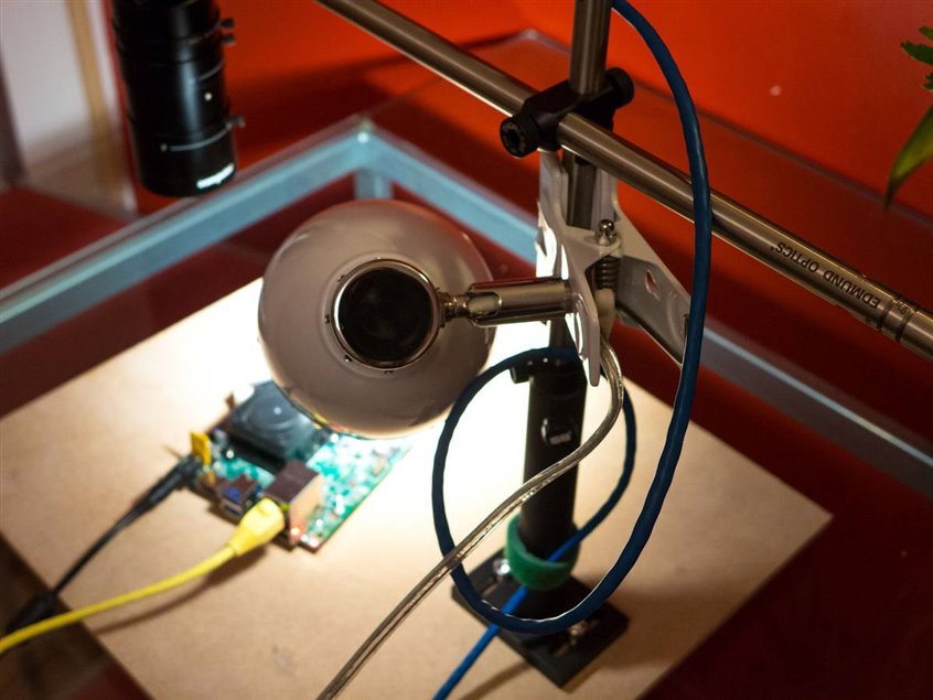
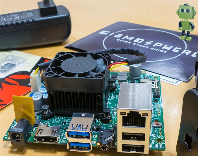
The camera stand assembly is shown below (the camera is inspecting its own Gizmo 2! – the blue and yellow cables go to a switch – see text further below). The assembly was mainly constructed from 0.5” diameter steel posts from Edmund Optics. Best practice is to use 1” or thicker for such designs, but 0.5” is much cheaper and worked fine. It is extremely stable, and can be rapidly swung out of the way if not needed.
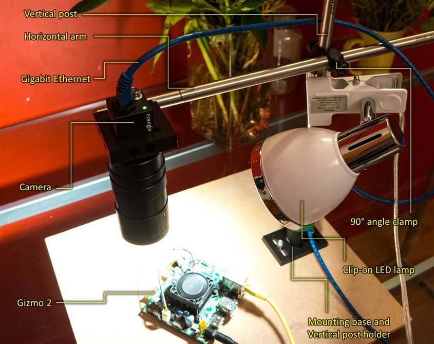
The angle clamp and mounting base was from Thorlabs. Not shown but important, there is a small thumbscrew-tightened collar underneath the angle clamp. It is needed to ensure the camera does not slam into the table accidentally whenever the clamp is adjusted.
Another view is shown below. The lamp (mains operated) was fitted with an LED lamp for a cool workspace. The Ethernet cable was held in place with Velcro. The assembly is just bolted to a piece of wood for now –it could be screwed directly onto a wooden table.
The camera is connected to the horizontal arm as shown below, using a flattened post from Thorlabs
Here is an example image (camera positioned about 30cm away from the PCB):
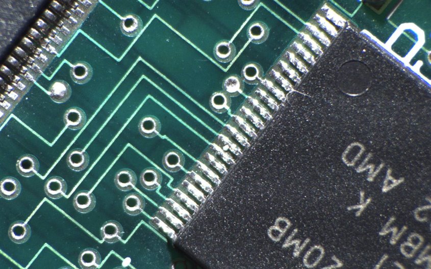
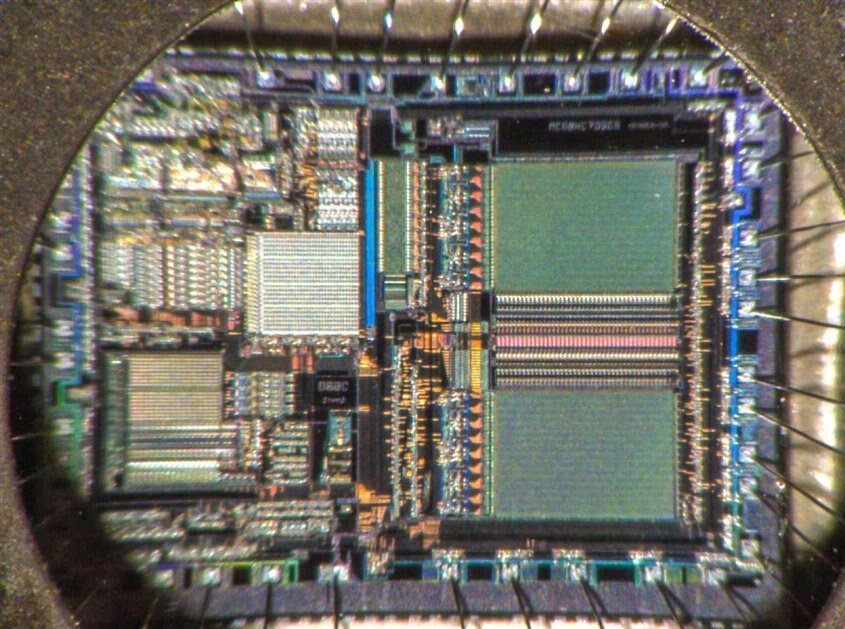
Although not intended for integrated circuit die examination, this is the view looking inside a Motorola 68HC11 microcontroller (a point-and-shoot camera with macro capability would provide a better static photo, but this photo is from a video stream of course:
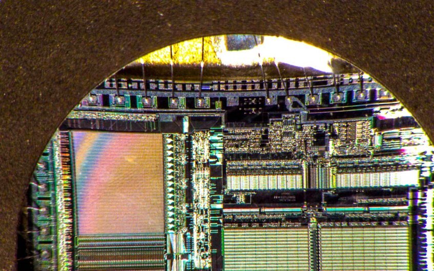
The image would be better with the die bare, but it is still clear that the lens is sharp enough for good detail.
Here is a 68HC705 device:
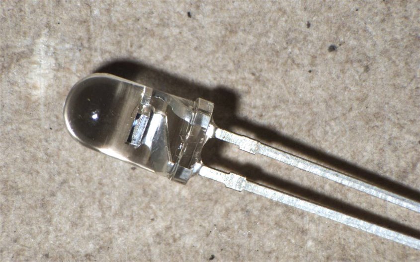
Some more photos just for fun. This is looking inside a 5mm red LED:
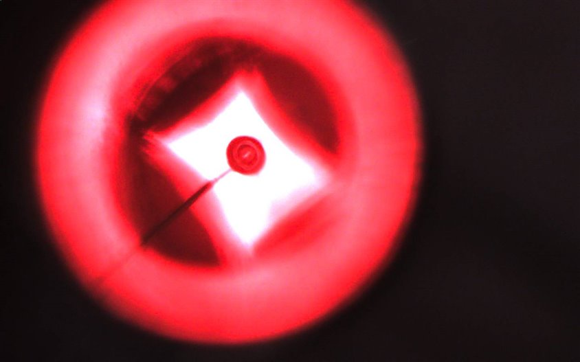
A BPV10 photodiode:
Using a Gigabit Ethernet Switch
The next step was to integrate the camera into the home network. A Gigabit Ethernet switch is needed with jumbo frame capability (not all support this, so definitely check! Also, don’t assume that the capability is enabled on the switch by default – usually it needs to be configured).
Jumbo frames are packets of data (payload and header, also known as an Ethernet Frame) with a larger size than that defined in the Ethernet standard. Throughput can be increased by using jumbo frames because less header content is transferred on average compared to the payload volume.
Power over Ethernet (PoE) capability is a nice-to-have feature because then just a single cable needs to connect to the camera and you get the benefits of energy efficiency and remote management and control. There are several PoE standards in existence. If you’re purchasing a new switch then ensure it has PoE+ capability at a minimum (also known as IEEE 802.3at-2009) and then the switch will be useful for powering many types of modern devices.
The PC network adapter in Windows was configured to enable jumbo frames up to 9014 bytes (to do this, navigate to the network adapter’s Network Connection Properties dialog and then select the Jumbo Packet property and set to 9014 bytes in the drop-down selection). Note that if you also use your PC to connect to other networks then you may need to disable this setting after you’ve finished using it with the camera.
If you are using Linux then issue the command
/sbin/ifconfig eth0 mtu 9000
(change the text ‘eth0’ as required).
If you want the property permanently set in Linux (i.e. to survive after a reboot) then type the line above into the /etc/rc.local file just before the ‘exit 0’ line at the end of the file.
There are some other network performance parameters; they are discussed further below.
Gizmo 2 – A Brief Introduction
I didn’t want to have to dedicate a PC for microscope use, so it was decided to try to use the Gizmo 2 for this task. The Gizmo 2 is a small (compact disk sized footprint) single board computer (SBC) with some advantages that made it suitable for the task. The Gizmo 2 has a Gigabit Ethernet interface which is needed but it also has a 64-bit x86 processor and this is needed when running GigE cameras that are supplied with x86 drivers. It is also possible to connect up plenty of local storage which is useful when storing HD video. Check out the Gizmo 2 getting started blog post which explains how to install a solid state drive (SSD) and install Linux.
I installed Ubuntu (release 14.04.1, not 14.04.2 – the latter has a bug which impacts the installation of development packages so it is better to first install 14.04.1 and then upgrade).
The Point Grey camera has Linux software called flycap which can be installed (the steps are described at their website) and the installation on Gizmo 2 was straightforward.
Improving Network Performance
By default the Gigabit Ethernet interface will not perform very well. After jumbo frames have been enabled (see earlier) some performance tuning is also needed and this is achieved by appending the following lines to the /etc/sysctl.conf file:
# improve performance for GigE cameras
net.core.rmem_max=4194304
net.core.rmem_default=4194304
With the flycap software running, the stats at the bottom of the window should say that the Proc/Disp/Req values are approximately 27Hz / 5Hz / 27Hz. This signifies good network throughput, but that the graphics driver is causing low frame rate. I was able to achieve 10Hz by reducing the requested frame rate in the configuration settings in the Point Grey flycap software. 10Hz is not bad for microscope use.
Upgrading the Graphics Driver for the Gizmo 2
Attempts to upgrade the graphics driver did not result in an improved frame rate for my particular application, and video tearing effects occurred unless the display resolution was reduced. I suspect this is due to limited RAM but I will continue to investigate. Another reason is that perhaps the application is still using old libraries that are in the library path. It is for further investigation but for now I’m happy with the 10Hz frame rate – it allows me to proceed with SMD work easily. I will revisit it and consult with AMD if possible because I'm sure a higher frame rate is achievable (Timesys managed it in their supplied demo for instance).
Two versions of graphics drivers were tested. The procedure to install the graphics driver is described here:
- Navigate to the AMD download website and scroll to the Manually Select Your Driver section
- For steps 1-4 on that page, select Embedded Graphics, Radeon Embedded, G-Series SOC 2nd Gen (Steppe Eagle) and Linux x86_64
- Download the desired driver version (I use the latest 15.101.1007 version dated 7/6/2015 but also selected ‘Previous Embedded GPU and APU Drivers’ and also downloaded the 14.502.1015 version)
- Once the zip file has been downloaded, unzip it and from the extracted folder run the installer from a terminal window (ideally from a desktop view not SSH, because there is a graphical installer and it is easier to use from a desktop view). The command to run the installer will be ./amd-driver-installer-15.101.1007-x86.x86_64.run
- When run follow the prompts. It will appear to hang for a very long time (perhaps 20 minutes or more with a progress bar that is at zero) but in the background the driver will be built. Eventually the build will complete and give you the option to install it.
- Execute aticonfig --initial after completion and then reboot Gizmo 2
- Reboot after the install is complete, and then from the Ubuntu desktop view hit the Ubuntu start/search icon and type amd to find and run the AMD Catalyst Control Center (administrator view). From here you can change driver settings if required.
Aravis – An Open Source Camera Library
Although the Point Grey camera comes with application software called Flycap, it is good to get Aravis functioning too because it allows for custom software modifications if desired. The Aravis install steps described here were followed and it ran successfully.
Summary
This post was slightly longer than expected, but the key points are that some handheld magnifiers are actually quite usable for occasional SMD work. Construction of an uncompressed HD microscope system for PCB inspection was presented, using mainly off-the-shelf components and the Gizmo 2 running Gigabit Ethernet.
Top Comments