element14 Community
element14 Community
    Register Log In
  • Site
  • Search
  • Log In Register
  • Community Hub
    Community Hub
    • What's New on element14
    • Feedback and Support
    • Benefits of Membership
    • Personal Blogs
    • Members Area
    • Achievement Levels
  • Learn
    Learn
    • Ask an Expert
    • eBooks
    • element14 presents
    • Learning Center
    • Tech Spotlight
    • STEM Academy
    • Webinars, Training and Events
    • Learning Groups
  • Technologies
    Technologies
    • 3D Printing
    • FPGA
    • Industrial Automation
    • Internet of Things
    • Power & Energy
    • Sensors
    • Technology Groups
  • Challenges & Projects
    Challenges & Projects
    • Design Challenges
    • element14 presents Projects
    • Project14
    • Arduino Projects
    • Raspberry Pi Projects
    • Project Groups
  • Products
    Products
    • Arduino
    • Avnet & Tria Boards Community
    • Dev Tools
    • Manufacturers
    • Multicomp Pro
    • Product Groups
    • Raspberry Pi
    • RoadTests & Reviews
  • About Us
    About the element14 Community
  • Store
    Store
    • Visit Your Store
    • Choose another store...
      • Europe
      •  Austria (German)
      •  Belgium (Dutch, French)
      •  Bulgaria (Bulgarian)
      •  Czech Republic (Czech)
      •  Denmark (Danish)
      •  Estonia (Estonian)
      •  Finland (Finnish)
      •  France (French)
      •  Germany (German)
      •  Hungary (Hungarian)
      •  Ireland
      •  Israel
      •  Italy (Italian)
      •  Latvia (Latvian)
      •  
      •  Lithuania (Lithuanian)
      •  Netherlands (Dutch)
      •  Norway (Norwegian)
      •  Poland (Polish)
      •  Portugal (Portuguese)
      •  Romania (Romanian)
      •  Russia (Russian)
      •  Slovakia (Slovak)
      •  Slovenia (Slovenian)
      •  Spain (Spanish)
      •  Sweden (Swedish)
      •  Switzerland(German, French)
      •  Turkey (Turkish)
      •  United Kingdom
      • Asia Pacific
      •  Australia
      •  China
      •  Hong Kong
      •  India
      •  Japan
      •  Korea (Korean)
      •  Malaysia
      •  New Zealand
      •  Philippines
      •  Singapore
      •  Taiwan
      •  Thailand (Thai)
      •  Vietnam
      • Americas
      •  Brazil (Portuguese)
      •  Canada
      •  Mexico (Spanish)
      •  United States
      Can't find the country/region you're looking for? Visit our export site or find a local distributor.
  • Translate
  • Profile
  • Settings
BeagleBoard
  • Products
  • Dev Tools
  • Single-Board Computers
  • BeagleBoard
  • More
  • Cancel
BeagleBoard
Blog BBB - Building a DAC
  • Blog
  • Forum
  • Documents
  • Quiz
  • Polls
  • Files
  • Members
  • Mentions
  • Sub-Groups
  • Tags
  • More
  • Cancel
  • New
Join BeagleBoard to participate - click to join for free!
  • Share
  • More
  • Cancel
Group Actions
  • Group RSS
  • More
  • Cancel
Engagement
  • Author Author: shabaz
  • Date Created: 6 Jul 2013 7:19 PM Date Created
  • Views 16744 views
  • Likes 8 likes
  • Comments 126 comments
  • onsemi
  • audio
  • dac
  • bbb
  • texas_instruments
  • bb_black
  • beagle_bone_black
  • ti
Related
Recommended

BBB - Building a DAC

shabaz
shabaz
6 Jul 2013

Introduction

This project was about getting audio out of the BeagleBone Black. The aim was to have stereo audio, at least as good as an iPod. See further below for the circuit, and also a video showing it working.

Later, this project was used to build a PCB design (see below for the link to this part 2, and then the PCB was used to make a home Sonos-type hi-fi audio player (see the link to part 3 below).


The BBB has an on-board I2S interface, which makes interfacing an external DAC easy. The I2S interface is connected from the AM3359 processor to the HDMI chip (TDA19988) but it is not required for HDMI to be used in order to make use of the I2S interface. The I2S interface is brought out to some pins on port P9 (see here for details). It was encouraging that Technoshaman and Donald Miller had some success with the interface, so I wanted to try it out and I got some time today.


Part 2 to this post, which implements the prototype, can be found by clicking here.
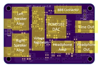
image

Part 3 implements a complete design in an enclosure for a Sonos-like solution.
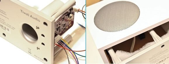
image

See Creating an Internet Radio for a complete project by the EAGLE team including board layouts
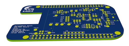
image


Parts Selection

Since the interface is capable of 24-bit/192kHz audio, it was worthwhile picking a nice DAC. A good but not over-the-top device seemed to be the Texas Instrument's PCM5101 which is nice because it has reasonable specs and also provides a built-in charge pump so that it can function from a single supply. A headphone amp was connected, and this was ON Semi's NCP2811A. The combination of PCM5101 (actually my prototype used PCM5101A which can also function from 1.8V, but this was not needed)  and NCP2811A was chosen so that the entire circuit could operate from the BBB supply if desired, even if it was from a Li-Ion battery that was powering the BBB, and for low noise and distortion. The only problem is that the PCM5101 has quite a high output (clearly a good thing!) but the audio amp minimum recommended gain is 1 and it cannot meet the required output voltage, and it means that it will distort at high volume. So, at a lower volume (and lower SNR) it will be fine, and I prefer this particular amp because of the very low distortion. The ON semi datasheet was sparse though.


Building It

This is the DAC prototype:
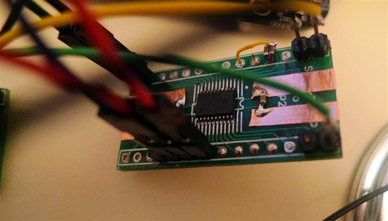
image

This is the whole thing connected up:
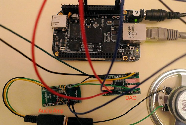
image

This is the rear of the board - a bit messier! It was built on a SMD to DIP adapter board with some copper tape for supply rails:
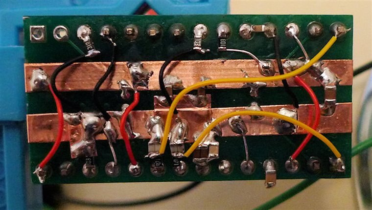
image

This is the audio amp - not a lot to it, since it is so integrated.
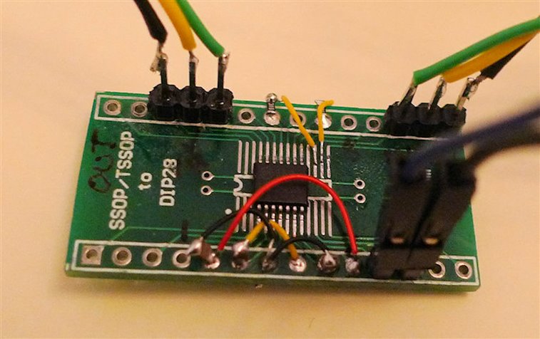
image


Testing It

I made a recording, but excuse the quality. The audio is from a small 64 ohm speaker picked up by a simple camera in-built microphone so it sounds bad, but connecting to headphones is a different story - it sounds as good as an ipod (although this is subjective - I don't have a way to measure). Another thing I still need to check is that originally I thought the data was read on the falling edge of the bitclock on the BBB, but I2S specifies the opposite. Maybe I made a mistake in my initial observations (I have not had a chance to re-check), or maybe it changed in a build. But the circuit as shown here works for me.


This is running on an not-recent Angstrom downloaded build (maybe a few weeks old image), and I still hear some very slight audio issues - it sounds like perhaps a break for a few tens of milliseconds occasionally, only if you're listening closely. I really hope it is resolved in a build soon (or maybe it is due to ffmpeg - perhaps avconv gives better results).

EDIT: I've since been using mplayer (command line is mplayer -ao alsa -volume 4 AmyWinehouse-BackToBlack.mp3  and either I'm not noticing any audio issues or they have disappeared). I've concluded it sounds at least as capable as my old ipod touch, maybe better).


I played audio using the command line:

ffmpeg -i AmyWinehouse-YouKnowImNoGood.mp3 -f alsa "default:CARD=Black" -re -vol 150

and it reported the stream as:

Stream #0.0: Audio: pcm_s16le, 44100 Hz, stereo, s16, 1411 kb/s


You don't have permission to edit metadata of this video.
Edit media
x
image
Upload Preview
image


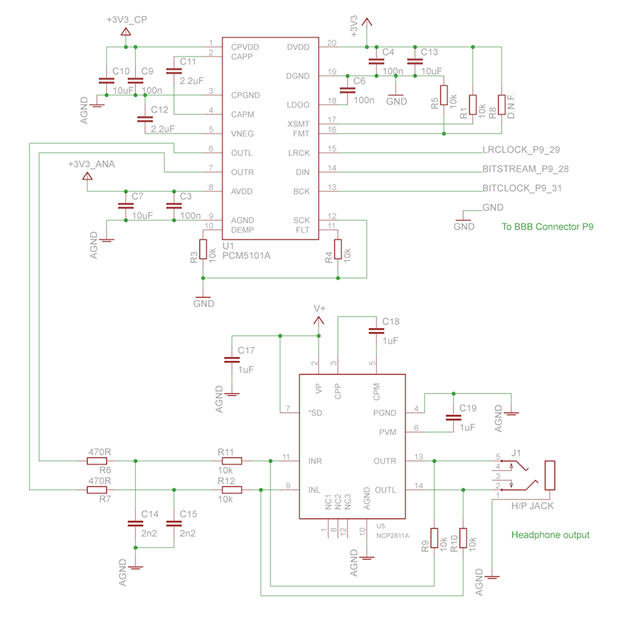
Circuit Diagram

This is the circuit. All the 3.3V supplies were connected together for the prototype (I wouldn't do that for real, although it sounded very good in my limited tests). The amplifier V+ can be connected to 3.3V or the 5V supply (or the Li-Ion battery directly).

Note 16th Jan 2014: See the comments section below for more detail; the SCK pin on the PCM5101A was disconnected from 0V and instead connected to the BBB P9 pin 25. This will provide the lowest jitter by disabling the DAC's internal PLL. A sample capture of the audio quality (captured from the headphone output of the NCP2811A, just to give an approximate idea of what it sounds like from headphones) is attached to the post below, in the zip file dac-output.zip. More info on it in the comments section below.

Note 2: Please add a logic inverter to the bitclock connection. For more detail, see the comments below (search for the word 'bitclock' to make it easier to find). See the part 2 blog post, and the attached file there called dac-documentation.zip for the circuit diagram, showing the bitclock inversion. More recent BBB images may not need it, but it was certainly needed for the images I tested with.
image


Experiments with FLAC

I've also tried a FLAC file, but I'm hitting some limitation with ffmpeg it seems, and it picks a 16-bit format when it ought to be 24-bit. Meanwhile, avconv I couldn't get to work for MP3 or FLAC (it reported 'av_interleaved_write_frame(): Resource temporarily unavailable'). If anyone knows, any tips on how to play FLAC at 24-bit would be gratefully appreciated.


root@beaglebone:~# ffmpeg -i Taxman_2009_Digital_Remaster.flac -f alsa "default:CARD=Black" -re -vol 5
ffmpeg version v0.8.4, Copyright (c) 2000-2012 the Libav developers
  built on May 20 2013 13:00:42 with gcc 4.7.3 20130205 (prerelease)
This program is not developed anymore and is only provided for compatibility. Use avconv instead (see Changelog for the list of incompatible changes).
[flac @ 0x2da80] max_analyze_duration reached
Input #0, flac, from 'Taxman_2009_Digital_Remaster.flac':
  Metadata:
    ORIGREFERENCE   : 6C05C9F79EE74052A7991B9669B98533
    ORIGDATE        : 2009:09:14
    ORIGTIME        : 11:57:01
    TIMEREFERENCE   : 5292000
    CODINGHISTORY   : A=PCM,F=44100,W=24,M=stereo,T=SADiE5
    ORGANIZATION    : EMI
    TITLE           : Taxman
    track           : 1
    ARTIST          : The Beatles
    ALBUM           : Revolver (24 BIT Remastered)
    DATE            : 2009
  Duration: 00:02:37.85, bitrate: 1892 kb/s
    Stream #0.0: Audio: flac, 44100 Hz, 2 channels, s32
Incompatible sample format 's32' for codec 'pcm_s16le', auto-selecting format 's16'
Output #0, alsa, to 'default:CARD=Black':
  Metadata:
    ORIGREFERENCE   : 6C05C9F79EE74052A7991B9669B98533
    ORIGDATE        : 2009:09:14
    ORIGTIME        : 11:57:01
    TIMEREFERENCE   : 5292000
    CODINGHISTORY   : A=PCM,F=44100,W=24,M=stereo,T=SADiE5
    ORGANIZATION    : EMI
    TITLE           : Taxman
    track           : 1
    ARTIST          : The Beatles
    ALBUM           : Revolver (24 BIT Remastered)
    DATE            : 2009
    encoder         : Lavf53.21.0
    Stream #0.0: Audio: pcm_s16le, 44100 Hz, 2 channels, s16, 1411 kb/s
Stream mapping:
  Stream #0.0 -> #0.0

Attachments:
dac-output.zip
  • Sign in to reply

Top Comments

  • e14 Contributor
    e14 Contributor over 12 years ago in reply to e14 Contributor +2
    Current test rig. BBB ($45), cs4271 on breadboard (about $15 parts and dozens of hours of labor), Cary Audio SE-1 amp (about $1K), pair of B&W DM302 speakers (about $200). I assembled this system that…
  • shabaz
    shabaz over 8 years ago in reply to shabaz +2
    Also, unrelated, but for after you have resolved the device tree issue, I just wanted to confirm, if you're following the circuit, make sure you include the 'bitclock inversion' functionality. The BBB…
  • shabaz
    shabaz over 8 years ago in reply to jithu_element14 +2
    Hi Jithu, Just to follow up on this, I re-tried on another image too, but still no luck. I've posted a request for help on the Beagleboard.org BBB-Wireless forum, in case anyone else has had success. Reproducing…
  • morgaine
    morgaine over 12 years ago in reply to shabaz

    shabaz wrote:


    This diag doesn't show a lot, but does highlight that it could be controlled via PRU if there was any need to do so, and that it has 4 stereo outputs (AXR0..3), so home cinema type applications are a definite possibility. In fact it seems superb for digital audio. Also, if desired, it can be programmed for direct S/PDIF (section 22.3.3.2 in the document), it doesn't need to be I2S.

    You've sure been doing a lot of reading! image


    It would be fun to drive 5.1 or 7.1 speakers from BBB multiplexed over a single S/PDIF connection.  For media centre applications, a board with full video decoding like Pi or the Allwinner-based OLinuXinos would be more appropriate, but for other multi-channel applications like MIDI musicians' instrumentation where video is not needed, this would be a viable network audio interface.


    Now that you've uncovered that S/PDIF can be output directly by the SoC, this opens up new possibilities since the PRUs are no longer tied up --- perhaps they could handle multi-channel input, or mixing, or network audio, or effects generation (like reverb and ducking), or more ambitious realtime MIDI synth or sequencer apps.


    That AM3359 sure has a lot of hidden talents, even in unexpected areas. image


    Morgaine.


    PS. There's no need to write a test program for this, as ALSA comes with a speaker-test program that can handle multiple channels.  For example,


    $ speaker-test -l 1 -c 5 -t wav

    0 - Front Left
    1 - Front Right
    2 - Rear Left
    3 - Rear Right
    4 - Center


    (It "speaks" the appropriate channel name, eg. "Front Left", on each channel in turn.)

    • Cancel
    • Vote Up 0 Vote Down
    • Sign in to reply
    • More
    • Cancel
  • shabaz
    shabaz over 12 years ago in reply to morgaine

    Hi! Good news, the tech ref manual and schematic reveals some really great things. Lots of copy/pasting of diagrams here to summarize things (since it is hard to keep paging up/down through the 4000 pages):

    This is the block diagram of the MCASP subsystem, which is used for the audio functionality. Specifically, we're interested in MCASP0. This diag doesn't show a lot, but does highlight that it could be controlled via PRU if there was any need to do so, and that it has 4 stereo outputs (AXR0..3), so home cinema type applications are a definite possibility. In fact it seems superb for digital audio. Also, if desired, it can be programmed for direct S/PDIF (section 22.3.3.2 in the document), it doesn't need to be I2S.

    image

    This diagram below shows it all in more detail:

    image

    The blue circled pins in the diagram above are used for the bitclock and the left/right frame clock in I2S mode. Normally these are outputs, but they can be inputs. But, alternatively, there is a pin which can be used for the high-speed clock (e.g. 256 times sample freq) from which the internal logic can be clocked. It is shown in red above, and this can be an input pin. See here:

    image

    This high-speed clock pin (MCASP0_AHCLKX) can be seen on the schematic, connected to a wire labelled GPIO3_21 (it goes out to the header P9 pin 25). This is great news, that we have access to the clock!:

    image

    The next bit was the realisation that it is already likely an input pin, since there is already a dedicated oscillator on the board.

    image

    So, the great thing is that we can use this clock (i.e. on GPIO3_21 which is already brought out to a P9 pin 25 as mentioned earlier) for clocking a DAC! The other cool thing is that with no driver mods, it would be possible to also generate an S/PDIF output using a S/PDIF transmitter IC clocked from here too. Of course the driver could be modified to generate S/PDIF anyway (so that no external IC is needed), but personally I'd rather have it as I2S so that the external board could be used for driving a DAC for headphones while simultaneously outputting S/PDIF for external hardware.


    So, to summarize, we can achieve low jitter for a DAC and for S/PDIF transmission (of course the receive side will stilll need to extract the clock so nothing we can do about that) very easily.


    I will try this on my DAC prototype (currently it is using the DAC's internal PLL capability) by connecting to P9 pin 25 and see if it works.

    • Cancel
    • Vote Up 0 Vote Down
    • Sign in to reply
    • More
    • Cancel
  • e14 Contributor
    e14 Contributor over 12 years ago in reply to shabaz

    My speaker projects. The vertical rectangular speaker on the left has two 8 inch mid-range and one 1 inch tweeter drivers. At bottom is the woofer which has two 12 inch drivers. On the right is my "sewer pipe" speaker, with one 5 inch mid-range/woofer (facing upwards at the top of the pipe) and one 1.5 inch tweeter. Sitting on top of the woofer is a 4 channel ATI 1800 power amp (180 watts per channel). Two channels go to the woofer, 1 channel to mid-range and 1 channel to tweeter. The power amp is driven directly from the RME ADI-8 DS DAC (not shown).

    image

    • Cancel
    • Vote Up +1 Vote Down
    • Sign in to reply
    • More
    • Cancel
  • shabaz
    shabaz over 12 years ago in reply to e14 Contributor

    Hi John,


    When replying, there should be a camera icon just above where the text is being entered, it will allow insertion of photos.

    • Cancel
    • Vote Up 0 Vote Down
    • Sign in to reply
    • More
    • Cancel
  • shabaz
    shabaz over 12 years ago in reply to morgaine

    Thanks for the link! It does seem that with standard audio consumer interfaces like optical, the recovered clock will have some jitter, so the best we can do at the transmission end is to try to ensure the transmitted data is clocked as clean as possible. I'm guessing some driver needs modification for the MCASP to accept an external clock. I'll try and read up more in this area..

    • Cancel
    • Vote Up 0 Vote Down
    • Sign in to reply
    • More
    • Cancel
<>
element14 Community

element14 is the first online community specifically for engineers. Connect with your peers and get expert answers to your questions.

  • Members
  • Learn
  • Technologies
  • Challenges & Projects
  • Products
  • Store
  • About Us
  • Feedback & Support
  • FAQs
  • Terms of Use
  • Privacy Policy
  • Legal and Copyright Notices
  • Sitemap
  • Cookies

An Avnet Company © 2026 Premier Farnell Limited. All Rights Reserved.

Premier Farnell Ltd, registered in England and Wales (no 00876412), registered office: Farnell House, Forge Lane, Leeds LS12 2NE.

Follow element14

  • X
  • Facebook
  • linkedin
  • YouTube