element14 Community
element14 Community
    Register Log In
  • Site
  • Search
  • Log In Register
  • Community Hub
    Community Hub
    • What's New on element14
    • Feedback and Support
    • Benefits of Membership
    • Personal Blogs
    • Members Area
    • Achievement Levels
  • Learn
    Learn
    • Ask an Expert
    • eBooks
    • element14 presents
    • Learning Center
    • Tech Spotlight
    • STEM Academy
    • Webinars, Training and Events
    • Learning Groups
  • Technologies
    Technologies
    • 3D Printing
    • FPGA
    • Industrial Automation
    • Internet of Things
    • Power & Energy
    • Sensors
    • Technology Groups
  • Challenges & Projects
    Challenges & Projects
    • Design Challenges
    • element14 presents Projects
    • Project14
    • Arduino Projects
    • Raspberry Pi Projects
    • Project Groups
  • Products
    Products
    • Arduino
    • Avnet & Tria Boards Community
    • Dev Tools
    • Manufacturers
    • Multicomp Pro
    • Product Groups
    • Raspberry Pi
    • RoadTests & Reviews
  • About Us
  • Store
    Store
    • Visit Your Store
    • Choose another store...
      • Europe
      •  Austria (German)
      •  Belgium (Dutch, French)
      •  Bulgaria (Bulgarian)
      •  Czech Republic (Czech)
      •  Denmark (Danish)
      •  Estonia (Estonian)
      •  Finland (Finnish)
      •  France (French)
      •  Germany (German)
      •  Hungary (Hungarian)
      •  Ireland
      •  Israel
      •  Italy (Italian)
      •  Latvia (Latvian)
      •  
      •  Lithuania (Lithuanian)
      •  Netherlands (Dutch)
      •  Norway (Norwegian)
      •  Poland (Polish)
      •  Portugal (Portuguese)
      •  Romania (Romanian)
      •  Russia (Russian)
      •  Slovakia (Slovak)
      •  Slovenia (Slovenian)
      •  Spain (Spanish)
      •  Sweden (Swedish)
      •  Switzerland(German, French)
      •  Turkey (Turkish)
      •  United Kingdom
      • Asia Pacific
      •  Australia
      •  China
      •  Hong Kong
      •  India
      • Japan
      •  Korea (Korean)
      •  Malaysia
      •  New Zealand
      •  Philippines
      •  Singapore
      •  Taiwan
      •  Thailand (Thai)
      • Vietnam
      • Americas
      •  Brazil (Portuguese)
      •  Canada
      •  Mexico (Spanish)
      •  United States
      Can't find the country/region you're looking for? Visit our export site or find a local distributor.
  • Translate
  • Profile
  • Settings
BeagleBoard
  • Products
  • Dev Tools
  • Single-Board Computers
  • BeagleBoard
  • More
  • Cancel
BeagleBoard
Blog BBB - Connecting up an LCD
  • Blog
  • Forum
  • Documents
  • Quiz
  • Polls
  • Files
  • Members
  • Mentions
  • Sub-Groups
  • Tags
  • More
  • Cancel
  • New
Join BeagleBoard to participate - click to join for free!
  • Share
  • More
  • Cancel
Group Actions
  • Group RSS
  • More
  • Cancel
Engagement
  • Author Author: shabaz
  • Date Created: 27 May 2013 10:26 PM Date Created
  • Views 3549 views
  • Likes 3 likes
  • Comments 7 comments
  • beaglebone_black
  • bb_black
  • beagle_bone_black
Related
Recommended

BBB - Connecting up an LCD

shabaz
shabaz
27 May 2013

Now that the BBB is becoming useful, it would be good to have some libraries of code and schematics to interwork it to a few popular sized displays. The BBB has a built-in LCD interface, i.e. a parallel high speed bus that can directly write to TFT displays. The LCD interface is connected to a TDA19988 chip on-board, which provides a HDMI output. The LCD interface is also brought out to header P8 so it is also possible to direct the output to an LCD. It would need some driver experience.


Another more simple approach is to use a serial interface, in which case the output will not reflect the Linux desktop.


This was rather easy, now that we know how to use the PRU to send high speed data (at least for GPIO1 currently). I just used a random color LCD and it worked fine.

The vendor electronics_lee on e-bay is selling lots of serial mode LCD displays (for less than $7 including free postage) of the type used in normal mobile phones (i.e. non-smartphones). The nice thing is that they can be run at a very high speed, so that video is possible if desired. It uses Sitronix ST7735 as the driver.


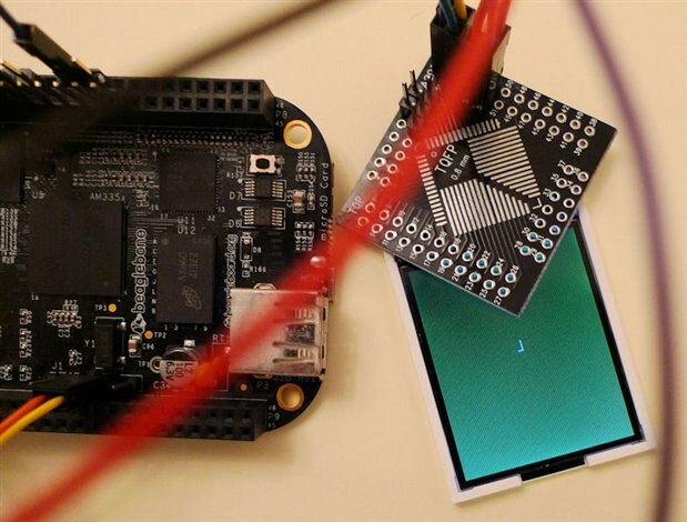
Currently the PRU code is used to initialize the display, set it all to a single color (green in this example) and then write the character 'L' to the center of the screen just as a test.

The entire screen is written in just tens of millisec, and it would be possible to speed it up further (I didn't read the datasheet closely for the timing specs). It would be good to get the PRU to populate the display based on RAM filled by software running on top of Linux, but I ran out of time to work on that (it should be simple to do).

image


The PRU code is attached if anyone wants to improve on it, to create a decent LCD library. For the Linux side for now, I just used the example code that comes with the PRU assembler.


The LCD is rather small (128x160 pixels, 34mm x 46mm in size, about 3mm thick) unfortunately, but good enough to display status information or a simple graph.


The LCD has only 14 pins, of which a couple are not used, and the GND pins are connected together already (the two VCC pins do need to be connected). The LED was connected to the 3.3V supply via a 100 ohm resistor, and the whole thing was powered from the BBB 3.3v supply.


image

The LCD looks like this unsoldered. Notice the small white strip, which is adhesive tape. This is used to stick it to the PCB to keep it in position while soldering (and then the display is folded over, so that the soldered flex is underneath the display).

image

image

The flex cable on the LCD has pins spaced 0.8mm apart, which was a perfect fit using one row of pins on a TQFP breakout board (it would be nice to make some custom PCBs for this display).

image

The photo above shows it soldered to the breakout board. It can be done with a normal soldering iron and normal solder, but if you have solder paste it makes it even easier. A really extremely tiny amount of the paste is spread in a line over the pads on the PCB, the LCD flex is stuck down with the adhesive tape in the photo earlier, and then a soldering iron is just stroked on top (outward, in the direction of the pads) to allow the paste to melt. There are small holes in the flex pads, so the solder will go through, so you can clearly see that it soldered correctly.


Viewing direction: I never understand how the clock system is used to specify the viewing direction on TFT displays, but basically the view appears best in landscape on this LCD, not in portrait. In portrait the screen goes bright/dim depending on if I look at it from above/below. In landscape it is much better. The backlight LEDs are on the edge closest to the flex cable.


This was the connections to the BBB, in order to use the attached PRU code:


LCD pin          Description          BBB header pin          Control reg Address

2,3                  GND,LEDK              P9 pin 1                   

6                    RESET                 P8 pin 26               0x44e1087c

7                    RS                    P8 pin 12               0x44e10830

8                    SDA                   P8 pin 16               0x44e10838

9                    SCL                   P8 pin 15               0x44e1083c

10, 11               VCC,VCC               P9 pin 3

12                   CS                    P8 pin 11               0x44e10834


LCD pin 4 (LED Anode) is connected to VCC via 100 ohm resistor.


The PRU code uses lots of macros, because the CALL and RET functions are emulated, and I don't think they can be nested (not really a major issue since there is lots of memory space for PRU code). I could be wrong.


Before you run the PRU code, make sure that the pins are set to  GPIO mode outputs in the device tree. For now I just did it in the .dtb file, but really it should be done in the .dtbo fragment. The configuration pairs are listed here (i.e. the least significant byte of the control register addresses in the list above, all set to 0x07 which is mode 7 GPIO output):

<0x30 0x7 0x34 0x7 0x38 0x7 0x3c 0x7 0x7c 0x7>


In the current code there is some junk instructions between lines 420-437 that are not needed, but I didn't get a chance to retest with them removed, so I left them in for now.

For the .hp file, just use any existing .hp file from the demos that come with the PRU assembler.

Attachments:
prucode_lcd.p.zip
  • Sign in to reply
  • bwelsby
    bwelsby over 12 years ago

    Nice one.

    There are 2 PRUs each with 8KB data memory, 8KB instruction memory and 12K shared ram. There should be enough code space to hold some basic graphics primitives.  In a former life I designed graphics systems used in industrial displays, before GPUs and such,  and I had to write all these from scratch in Z80 assembler. I'll have a see how easy it is to port to PRU assembly.

    • Cancel
    • Vote Up 0 Vote Down
    • Sign in to reply
    • More
    • Cancel
  • fustini
    fustini over 12 years ago

    Impressive series of blog posts!  Can't wait to see what you do next image

    • Cancel
    • Vote Up 0 Vote Down
    • Sign in to reply
    • More
    • Cancel
<
element14 Community

element14 is the first online community specifically for engineers. Connect with your peers and get expert answers to your questions.

  • Members
  • Learn
  • Technologies
  • Challenges & Projects
  • Products
  • Store
  • About Us
  • Feedback & Support
  • FAQs
  • Terms of Use
  • Privacy Policy
  • Legal and Copyright Notices
  • Sitemap
  • Cookies

An Avnet Company © 2026 Premier Farnell Limited. All Rights Reserved.

Premier Farnell Ltd, registered in England and Wales (no 00876412), registered office: Farnell House, Forge Lane, Leeds LS12 2NE.

ICP 备案号 10220084.

Follow element14

  • X
  • Facebook
  • linkedin
  • YouTube