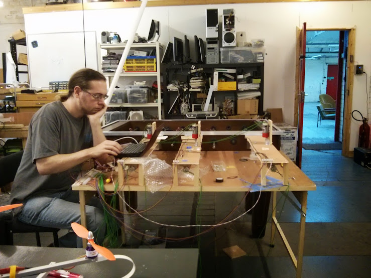
So we took this:
And ended up with this:
With Paul looking a bit perplexed at controlling the arms with the BeagleBone Black, the tracking actually works!
The above video is the OpenCV code tracking the direction of the ball and predicting where it will go so that the motors controlling the arms can react.
The above video shows the arms moving in reaction to the location of the ball; it acknowledges the location of the ball and tries to identify which player is best to 'chase' it, so that's why it seems a bit erratic at times.
It took a few weeks tracing through the technical reference manuals for the PRU along with misinformation on the internet to understand the pinmux and produce a table which actually made sense. Along with actually being able to share a document properly via Google Docs, hopefully this is now published and the file is available : PRU PinMUX Tables for reference.
This helped Paul along to do the code; which is on github: Paul's Python binding for PRUSS code for loading the PRU assembly and Paul's BeagleBone Football Code (PRU/Python/OpenCV) for ball tracking (OpenCV) and motor control.
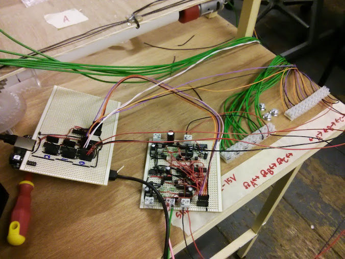
The motor control was effectively working as a shield with a custom pinmux table hacked together (we didn't bother using the dtc -@ to have a proper shield configuration and just hacked apart the default dtc because that worked) so here's the Circuit Design for Motor Control where the BeagleBone Black plugged into, which may not have the values stated at present along with the 12-20v Charge Pump for part of the Motor Control. The Playstation Eye (not Eyetoy) was used as the camera for the ball tracking.
On the left, hiding underneath is the BeagleBone Black, then connecting to the motor driver circuitry just for ease of use/soldering, which's then connected to the table for the motor movement.
There's also a plan for the goal scoring to be tracked by the BeagleBone Black, we installed infra-red sensors into the goals and proto-typed it with a Minimus32 modified with an Arduino bootloader for ease of use; this was going to be passed off onto the PRU but I didn't have (enough) time.
Pictures:
Previous blog posts:
Edit for More Information:
I had glossed over a lot of the detail above, but quite a bit of work went into doing this project, mainly because we weren't 100% clued up on how to use the BeagleBone Black best.
So for this build we didn't use the default Angstrum (sp?) linux on the BeagleBone but went with a distro we were familiar with, Debian. This was mainly because we intended on using SimpleCV as opposed to OpenCV because we thought it was a package that had been used before and were familiar with. Turns out it was actually OpenCV we'd used but we decided to stick with Debian anyway.
The custom build of Debian which was modified for the ARM processor didn't have an up to date device tree compiler (PinMUX file creator effectively, dts/dtc/etc) until a few weeks into the project, so we didn't focus on using the proper method for modifying the PinMUX settings and just looked at disabling the shields that are created by default. This's mainly for the HDMI, etc.
This tied in with finding out how the PRU actually worked; there was a lot of good examples on element14 and Hipster Circuits about how to interact with it but many were confused about how exactly to set the pins as input or output and not many good examples for the actual assembly code for using the PRU. After reading through the technical manuals for the chip on the BeagleBone Black, which mainly was the original version 'c' of the main ARM chips documentation we found the assembly commands and discovered about the registers, such that r30 is mainly hard wired/coded as output only and r31 as input. However these still had to be reflected in the PinMUX so the correct hex values had to be put in place, again discovered by further reading and hopefully the google doc I created will clear things up for people.
Though we've now learnt that you can pass kernel parameters to disable the shields, we hadn't found this information at the time and so rebuilt the kernel to have them all disabled by default. Paul Brook also found that there was a limitation in using OpenCV with an external USB Webcam, a problem I think with handling images from the Webcam, that could potentially be fixed in the kernel.
The cogs and braces for holding the poles and the motors to interface with them were laser cut at the Hackspace, this's a laser cutter that's on loan from NottingHack. Other parts were either sourced from our current stores or from our own pocket when visiting the Farnell trade counter and gleefully heckling the staff with some polite banter. Jon Stockill put the majority of it together and wired it up, along with the wood cutting for the desk and attachment to the table itself.
For the motor control the mechanism utilised endstops so that it didn't try to ram the table repeatedly or shoot off, we had to create a driver board for the motors because the nature of them and with them being 12v required a bit of adaptation to use them effectively. Basically this is an area I'm not entirely familiar with as Paul and Jon handled it so they can answer it better. We had devices attached to them so we could check how far they had moved/their location because we wanted the BeagleBone to be able to adjust the 'person' on the rod to where the ball was, etc.
With the ball tracking we discovered that it was best using two white LED strips above the table to help to illuminate it, while we 'blacked out' any unwanted white marks on the table and used an orange ball for high(er) contrast.
There really is a lot of code that went into this; so make sure to visit the github links above and check them out!


Top Comments